BrooksBots

RoboMagellan

FireBall

Videos

ExSpurt

ExSpurt Tires

ExSpurt Strategy

Executioner

Extrasensory II

Expressway

Extrasensory

Excuse II

75 lbs Sumo

Excuse

Expendable

Exhume

Mighty Man

Sticky

Flaming P'nut

Exert-O'Meter

Runt

Wall Follower

SPAR Videos

RoboMagellan

Purpose and Goals
During October, 2007, I received an Email from Steve Hassenplug. Steve was trying to get the Chicago robot club (Chibots) to hold an annual RoboMagellan contest. He needed some more entries, so I committed to build a robot for the spring, 2008 competition.

Chicago 2010 StartThe first goal was to learn the Parallax Propeller. All of my fun with robotics has involved the Basic Stamp for about seven years. I did experiment with other microcontrollers (SX, AVR, PIC, and Propeller) without much success (or lack of motivation). By the end of 2007, the Propeller Object Exchange was large enough to be useful and some learning tools were becoming available. Now, the RoboMagellan was the motivation to take the time to learn.

Chicago 2010 FinishThe second goal is to play with technology. GPS, compass, encoder, sonar, etc. sounded like fun. Also, new devices were coming on the market. I just needed an excuse to buy them, make them work, and incorporate the functions into a robot. It is all a lot of fun and has been a constant obsession ever since. I do get distracted often.

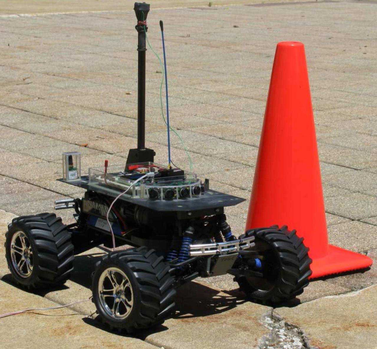
I really wasn't interested in finding pylons, but I wanted a robot that could navigate around outdoors, perhaps drive down the sidewalk or around the block. So all early work was done on a flexible platform that could function outdoors and incorporate a variety of sensors. Flexibility was important since I had no experience with existing sensors. Work with sensors in the past indicated that each new sensor would require time and testing to determine its true value and limitations. Locating pylons was added late in the project, almost as an afterthought.

The first two contests (Spring and Fall, 2008), this robot did not find anything useful and had a lot of problems with autonomous control. The robot won the next two contests (Chibots RoboMagellan 2009 and 2010) finding all three pylons consistently.

Chassis
Chassis Left SideWhen the RoboMagellan project was started, Traxxas was just introducing the new E-Maxx 16.8V monster truck. One was ordered as soon as they were available from Tower Hobbies (December 17, 2007). It arrived December 19, 2007 and the fun began. The E-Maxx was chosen because of its large size, reputation for reliability, and availability of accessories. Modification of the basic chassis was important since this application was far from the designed performance envelop.

Initial configuration of the carbon fiber top plate on the chassisA .062 carbon fiber plate (because I had one) was added to the stock body mount posts and all of the new electronics were mounted on a perforated circuit board on the plate. The front mount was later modified to allow the sonar sensors a clear view of the surface ahead.

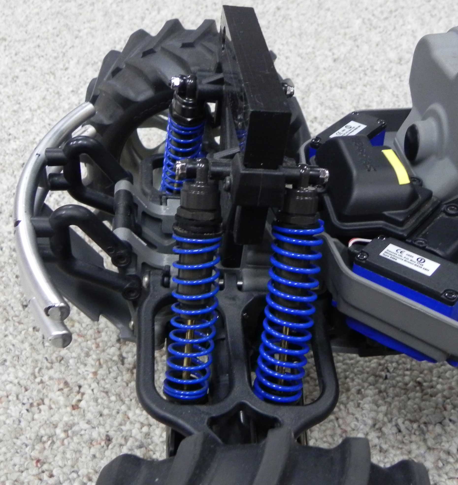
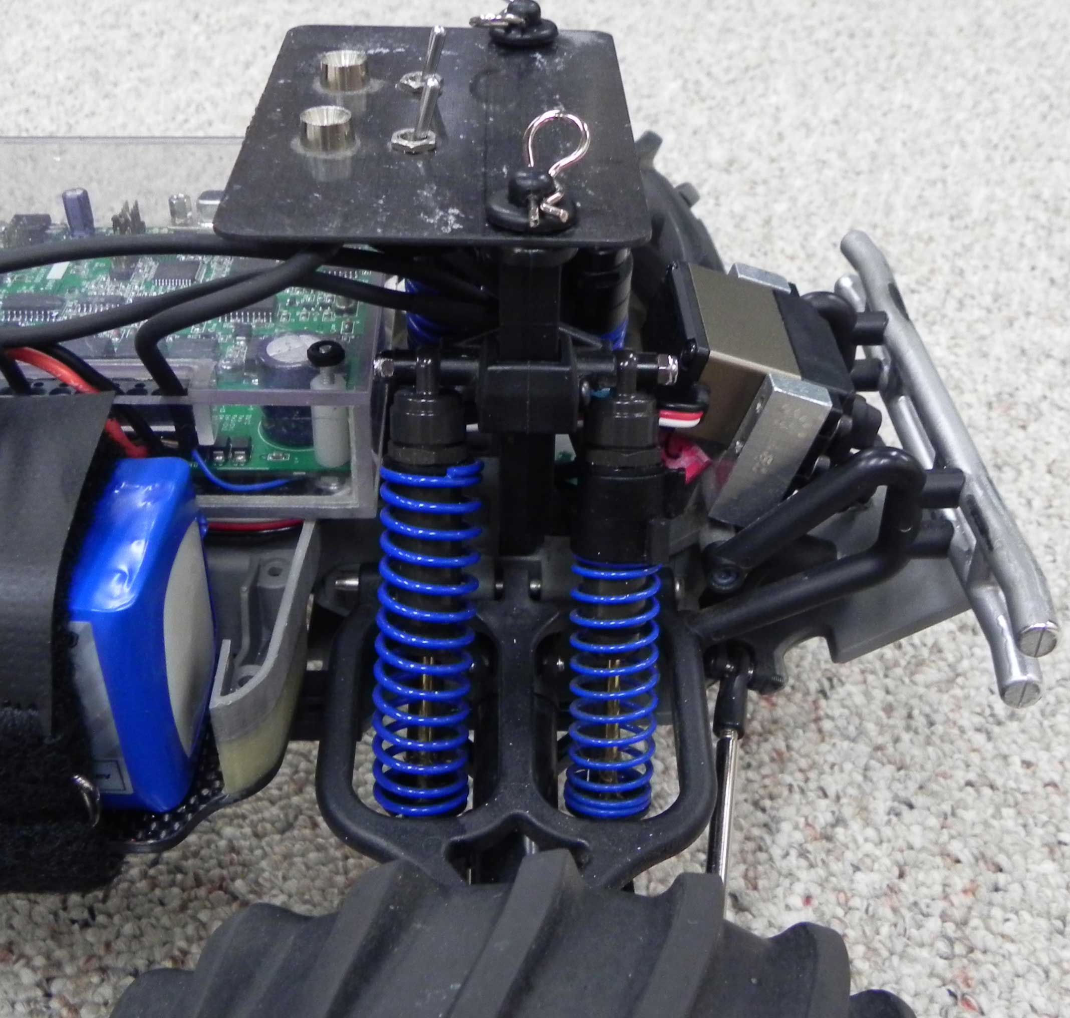
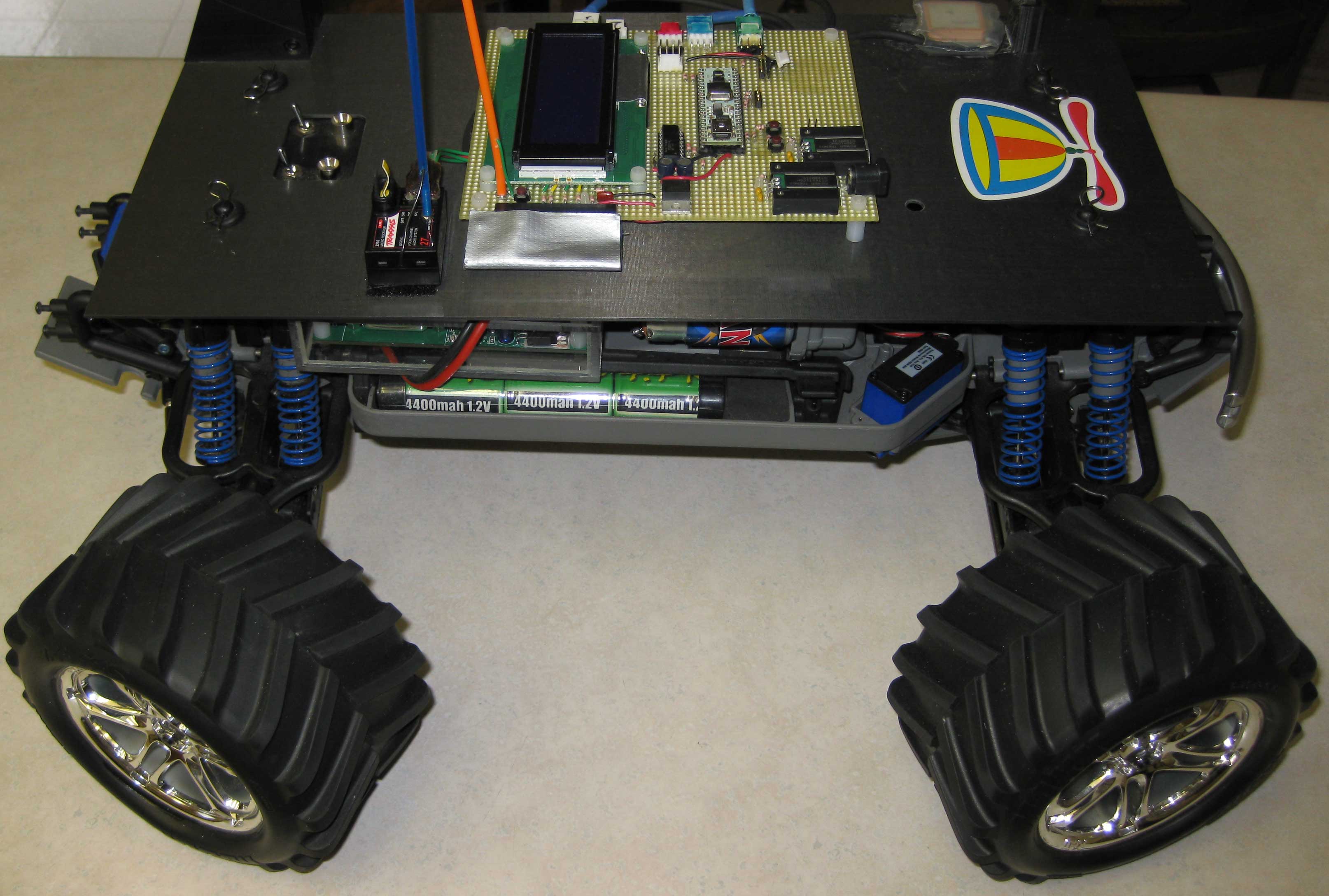
Initial running indicated that the stock springs were not capable of handling the added weight, so a local hobby shop provided the heaviest springs they could find. Additional spring spacers were added to level the chassis. That crude setup proved reasonable for early development.

Late in 2010 a serious attempt was made to stabilize the chassis of the robot. The chassis bounced around quite a bit leading to false hits from the sonar sensors. The increased weight of the robot appeared to be the primary problem. A set of Traxxas Big Bore Shocks was purchased, along with Heavy Duty Blue Springs from VG Racing. The Springs are .075" diameter compared to .062" for the Blue springs that have been used and .045" for the original Traxxas Red springs.

Front Springs and ShocksRear Springs and ShocksThe new springs and shocks proved to be way too stiff for the robot. The suspension did not absorb bumps, but just transferred the bumps to the chassis. Half of the springs were replaced with the older heavy duty Blue springs, so each corner had one .075" spring and one .062" spring. This combination appeared right for the front end, but was a little weak for the rear. Two large spacers were added to the rear .062" springs. The results are excellent. Running quickly over park like grassy areas produced a very stable platform for the sonar sensors. The robot still drops the front under heavy braking leading to false sonar hits that leads to heaver braking, but I don't have a solution for that problem, yet.

The current weight of the robot is 13.75 pounds.

Radio Control
Temporary radio control plug inThe Radio Control unit was removed from the Chassis, but having the R/C function available has proven to be very handy. The receiver was hooked up to the Propeller using standard Propeller Object Exchange functions and was used to test the motor and steering controls. The first "autonomous" movement was a three point reversing turn to test the accuracy and repeatability of autonomous movements. The robot would drive normally under R/C control. When the third channel was activated, the robot would do a three point reversing turn and then stop. When the third channel was deactivated, the robot would return to normal R/C control.

The next function was the development of gradual acceleration and deceleration performance. The Propeller limited the rate of change of speed in order to reduce tire slip on grassy surfaces. The point of this was to increase the accuracy of the encoder. In order to avoid obstacles, braking had to be far more aggressive than acceleration.

Stability of the robot was a primary concern. The E-Maxx can easily be flipped or rolled if too much steering is applied at too high a speed. In order to create stability, the Propeller did some processing of the incoming R/C signal before sending commands to the servos. First, maximum speed became a variable that was reduce as steering increased. Second, the actual speed was monitored with the encoder and actual steering output was limited based on that speed. There was some trial and error work here, but the end result was a robot that could not be flipped or rolled on reasonable surfaces and still respond very quickly to avoid impending obstacles.

The radio control continues to be an option. The receiver can be plugged into the control board at any time and there is a Propeller cog waiting to process a good signal from the receiver. The Propeller will recognize a good R/C signal if five good frames are received in a row where each channel and the frame timing is within acceptable limits. The radio control function has been used extensively in both sonar experiments and chassis tuning.
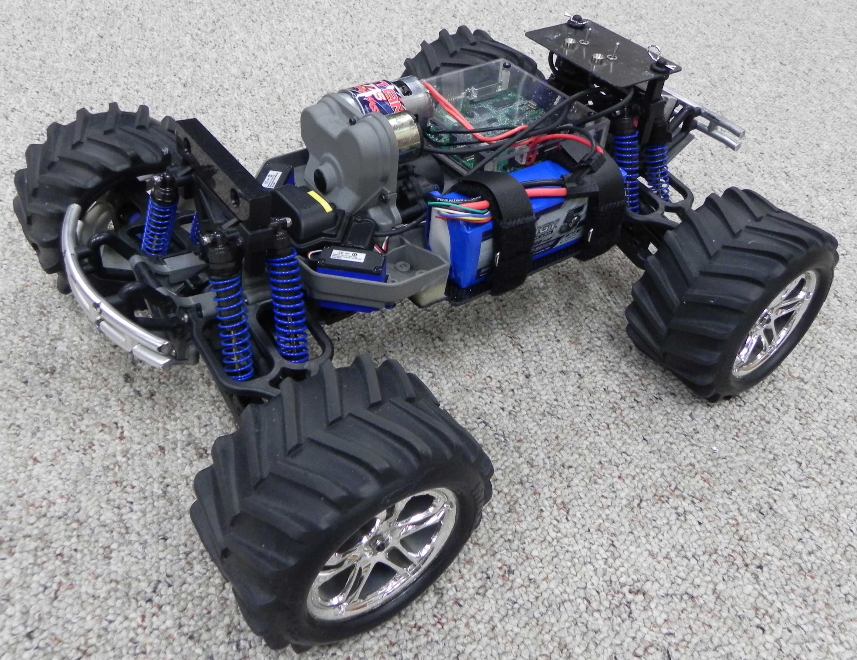
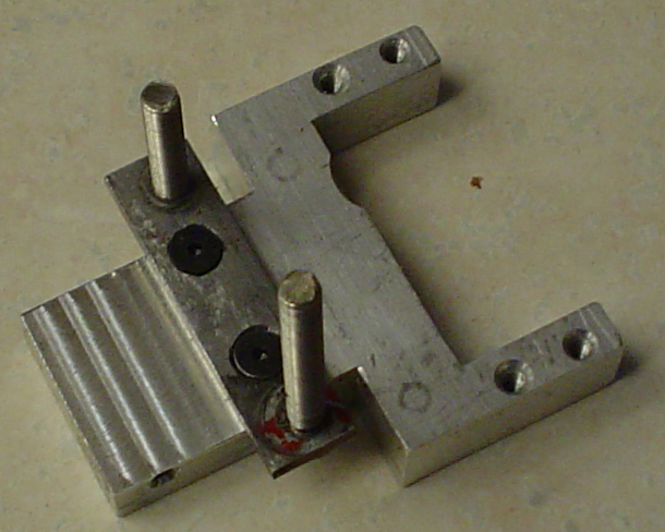
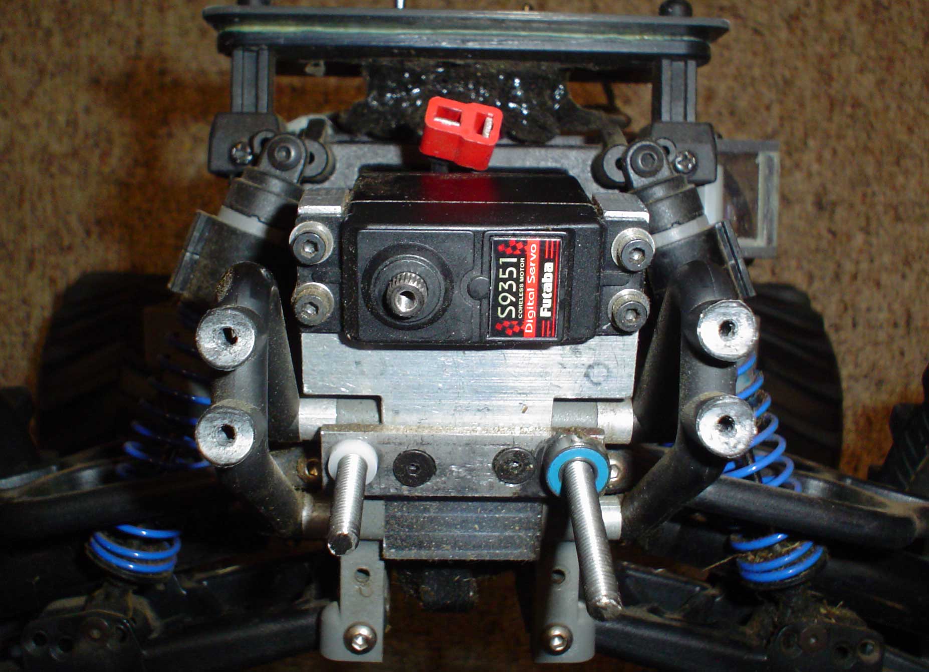
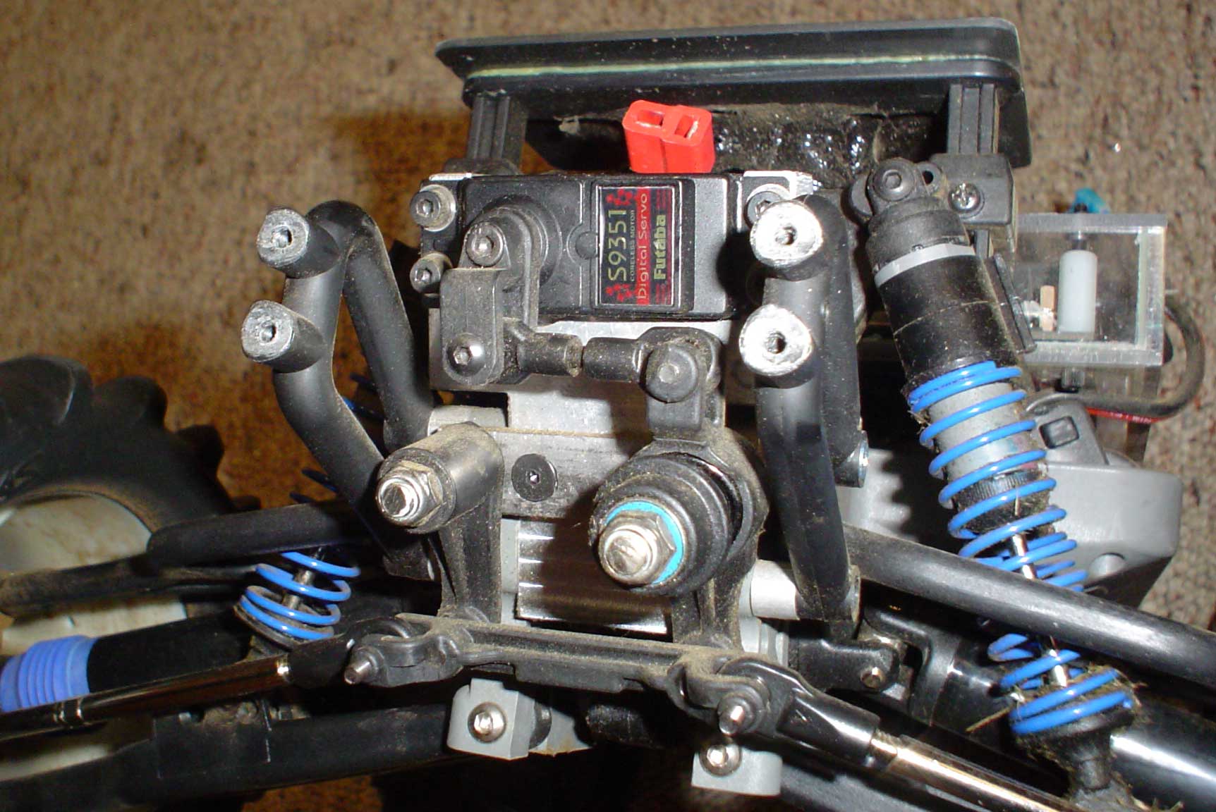
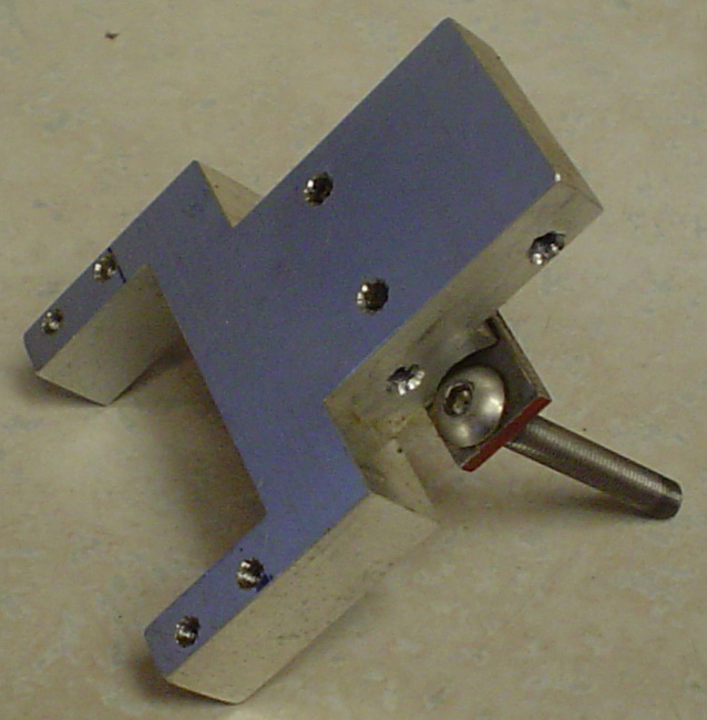
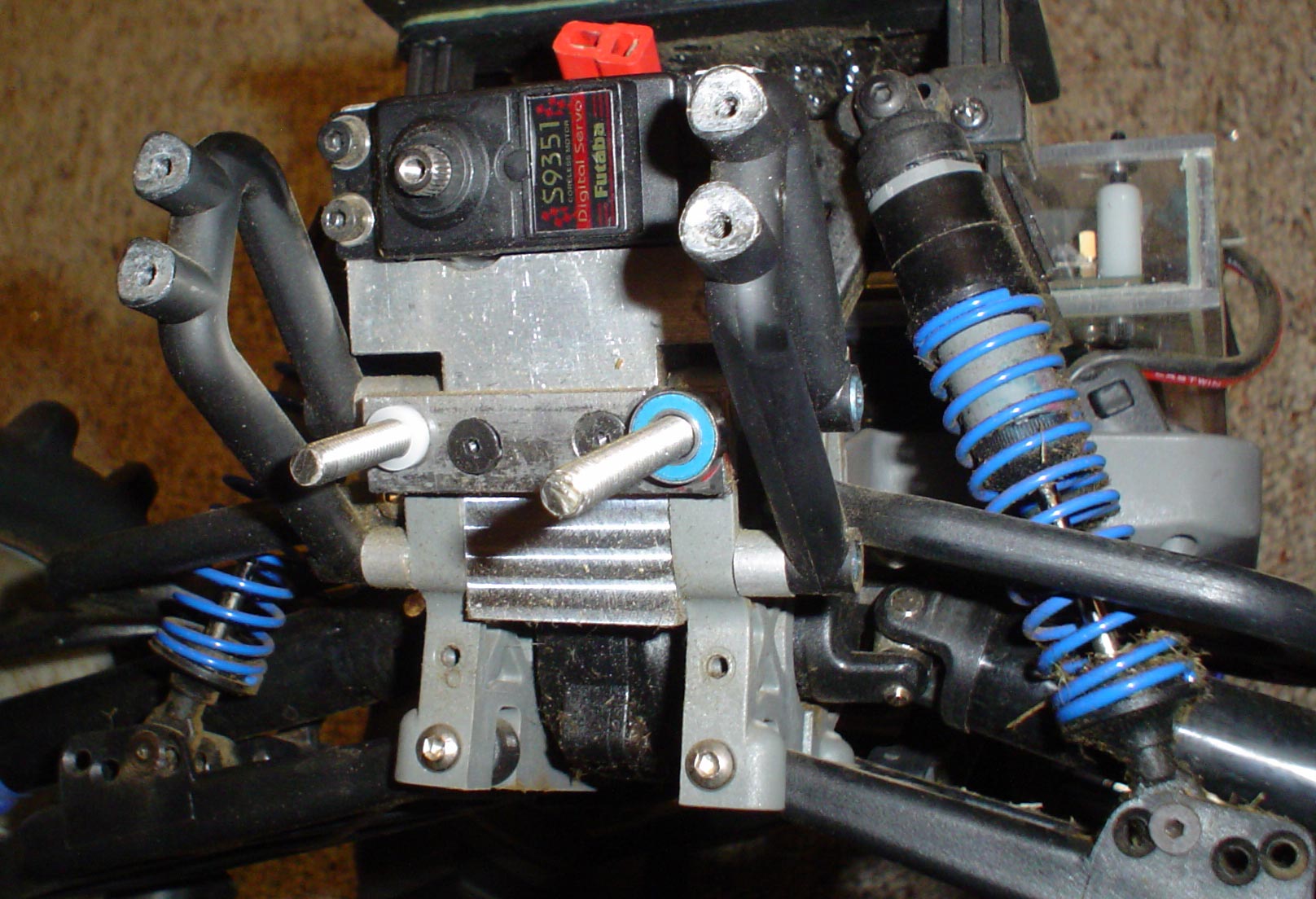
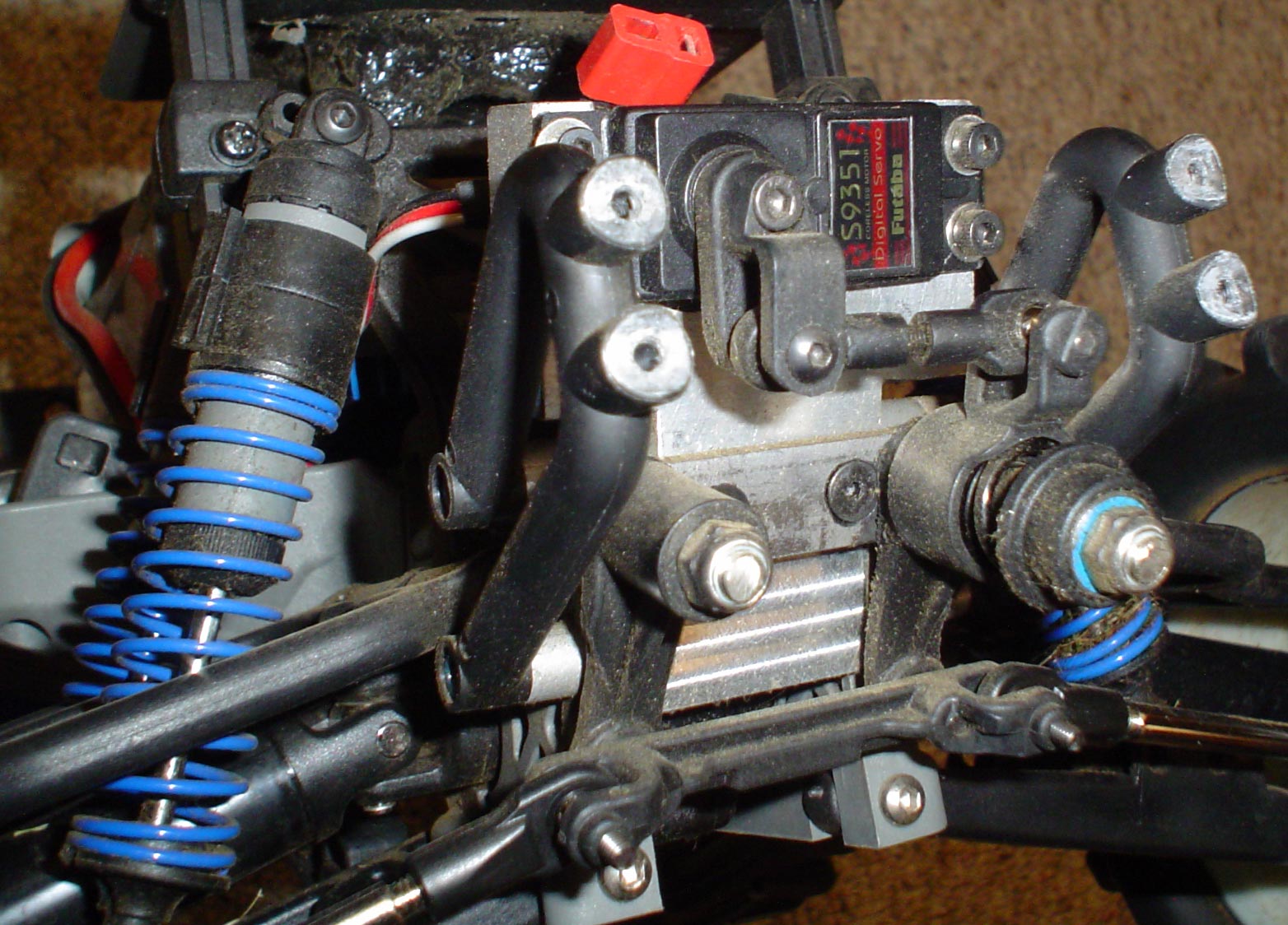
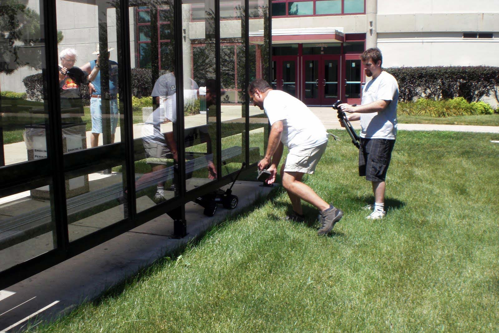
Rear Steer
Traxxas E-Maxx four wheel steeringInitially, the turn circle of the E-Maxx was 75 inches diameter. This may be reasonable for an R/C truck, but not a pylon seeking robot. Rear steer was required, but no kits were available for this version of E-Maxx. The Traxxas representative at iHobby Expo 2008 said that it was easy to do, but didn’t plan to introduce a kit. So a machined aluminum block replaced the rear bulkhead cross brace and provided a mount for the Futaba S9351 servo and the servo saver. It took four tries before the correct dimensions for the block were obtained. Excessive bump steer was a major problem and the iterations of the block design raised the servo saver and servo until bump steer was reduced to an acceptable level. The front and rear hubs and suspension arms of an E-Maxx are identical, making this conversion straightforward.

The below photos should give some idea of the rear steer design. Standard E-Maxx steering servo saver was used along with front end tie rods. The bumper mounting brackets had to be moved outward 0.25" to increase clearance for the steering mechanism.

Rear Steer Servo Mount Rear Steer Mount in Chassis Rear Servo Saver installed

Back view of Rear Servo Mount Angle view of servo mount installed in the chassis Rear Servo Saver mounted in servo mount

At low speeds the front steering provides 100% of the steering movement for the first 75% of the control range. The last 25% of the control range is done entirely with the rear steering, going form 0% steering movement to 100% steering movement. At speeds over 2 or 3 mph, original performance is enabled, i.e. all of the steering is done with the front steer and the rear steering is locked straight ahead. After the modifications the turning circuit is now a more reasonable 60".
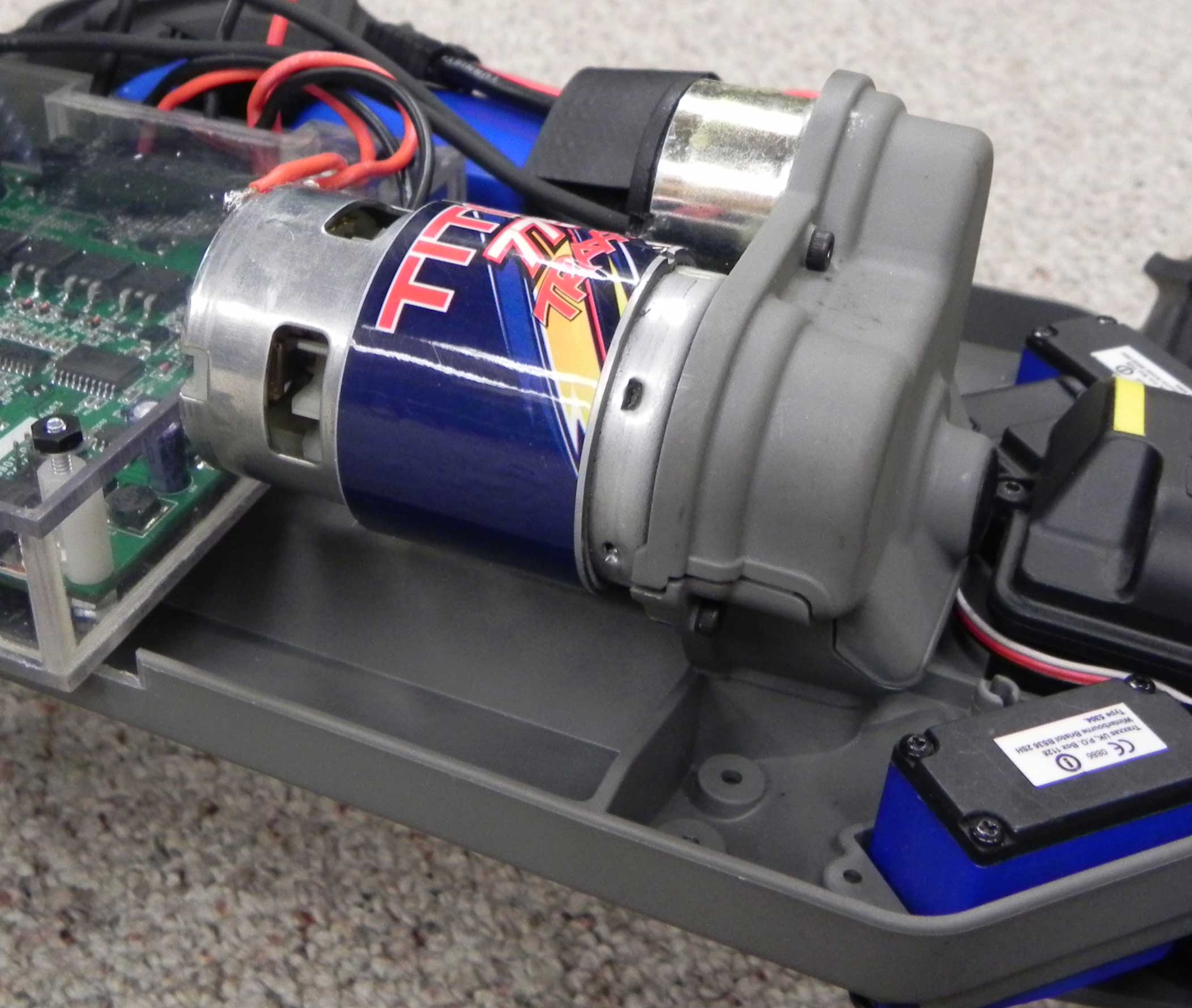
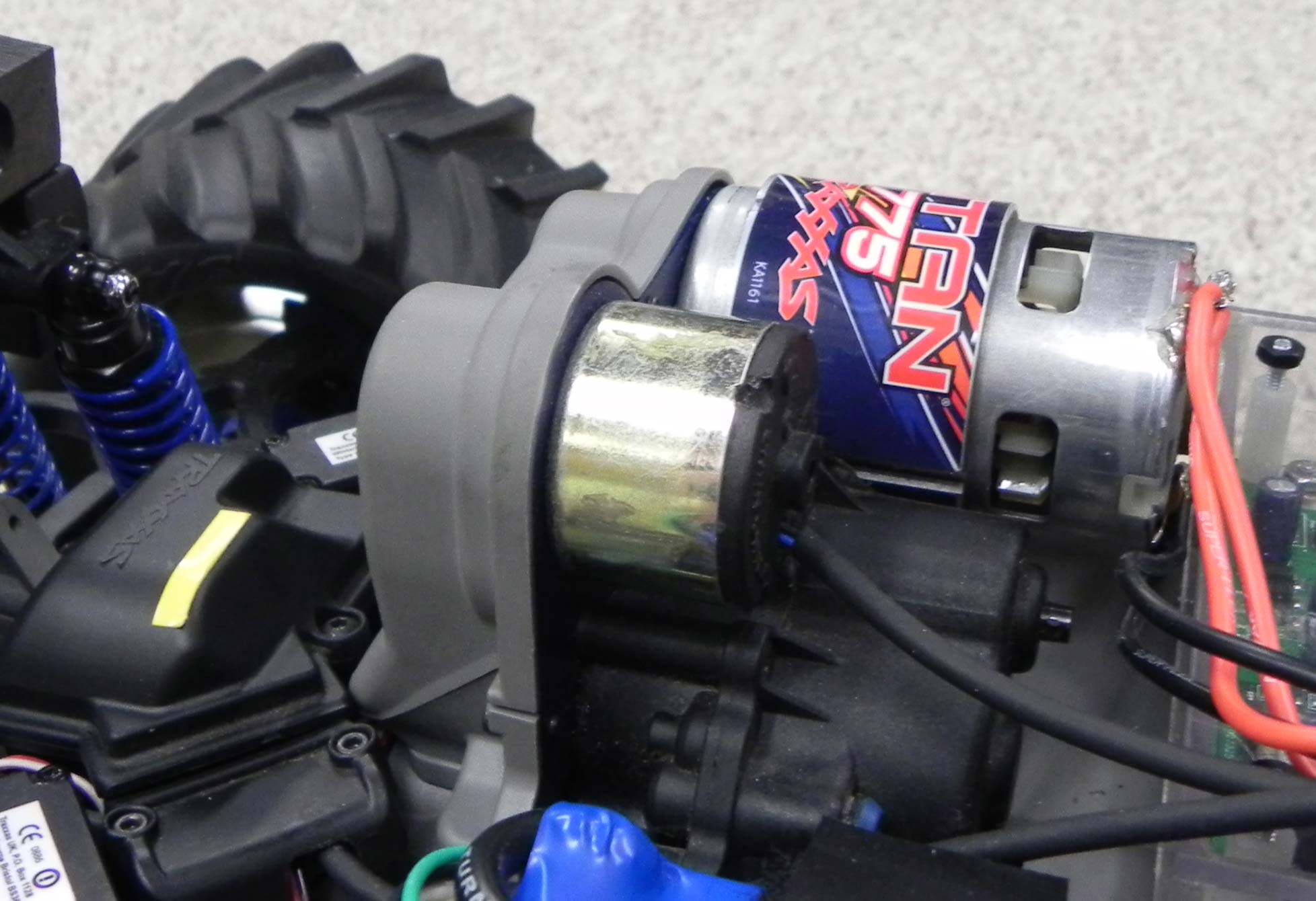
Motor
A typical R/C truck is way too fast for RoboMagellan. So, initial modifications were concerned with reducing speed. One motor was removed and the smallest pinion (12 tooth) was installed before the robot was first run. The stock 68 tooth spur gear was retained.

Even with the reduced gear ratio, the speed was too high and had to be limited with the microcontroller. Also, low speed performance on hills in thick grass was a problem, so a lower gear ratio was needed. To that end, a two speed transmission was added with the low speed gear permanently engaged. At the same time, the pinion was changed to 13 tooth. Finally, speed and torque were in a reasonable range.
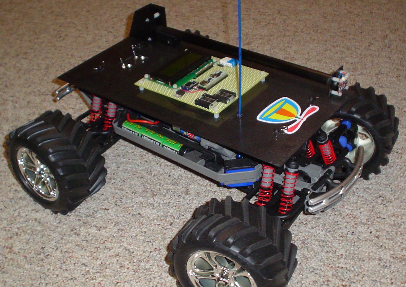
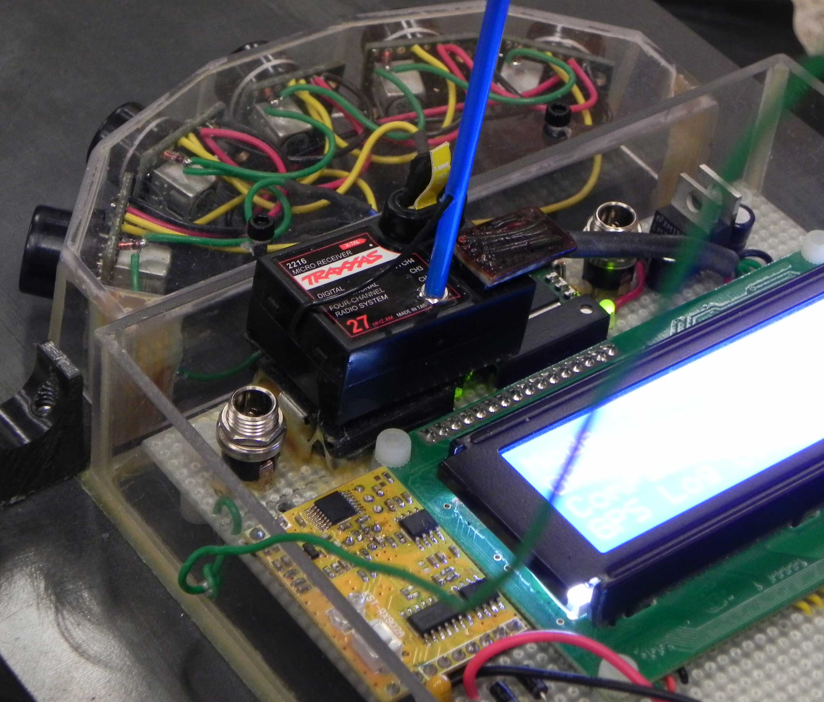
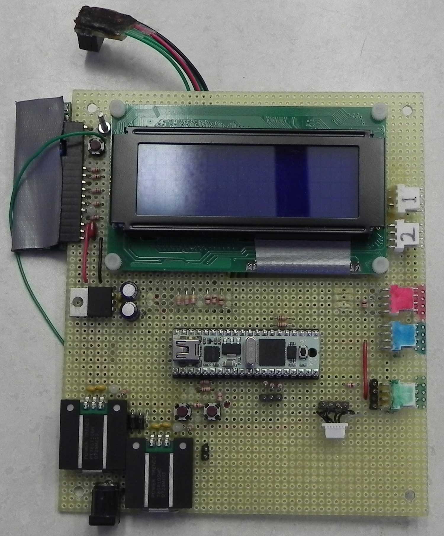
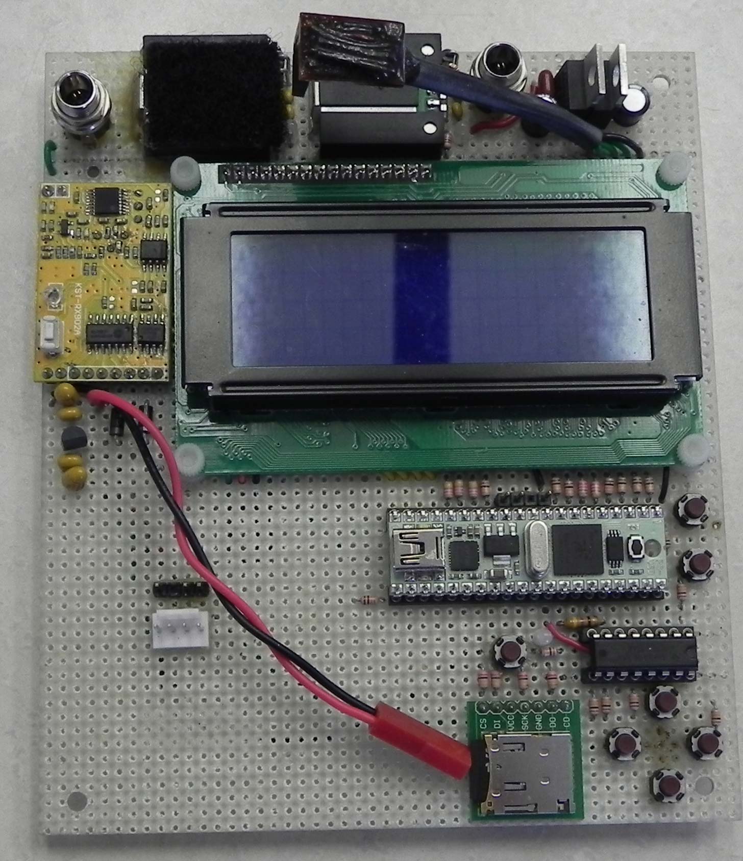
Traxxas 775 motorThere was still a substantial difference between uphill speed in thick grass and downhill speed on pavement. To make the speed more consistent, the original Titan 550 motor was replaced by a Titan 775 for 2010. For the first runs a 14/72 gear ratio was tried. It was soon changed to 15/72. The substantial torque increase of the 775 provided more consistent speed on all surfaces. Plus the slightly higher gear ratio on the 775 increased top speed.

Electronics
Original control board Revised control boardThe major component on the Control board is a Parallax Propeller in a PropStick USB configuration. It is mounted in a socket for easy modifications, and there were many, many modifications. The major advantage of the Propeller is the eight separate microcontrollers sharing a common memory. This will allow each hardware interface to be developed separately without impacting all other processes that may may also be in development or completed and in use.

The display is a 4x20 character LCD from Comfile Technology Inc. The back light allows the display to be easily read in direct sunlight. The advantage to this LCD is the serial interface rate of 115,200 baud that allows for very fast updates. Actually, even more speed was required, so only one line of display is updated during each control loop. In the Fall of 2008, there was a problem with the LCD in outdoor testing. Apparently, the resonator was cold sensitive. The manufacture was very helpful identifying the problem and providing replacements. Now, each new or revised board is run for an hour or two in the freezer to assure cold weather performance.

The board contains three voltage regulators, a switching 6 volt (PT78ST106H) for the servos, a switching 5 volt (78SR105HC) for some electronics, and a linear 3.3 volt (LM2937ET-3.3) for the rest of the electronics. Soon, it was discovered that the sonar units do not work well on a switching power supply, so a linear 5 volt (LM2940CT-5.0) regulator was added. Later, it was found that the the GPS performs better if it remains powered on all the time. A small Lipo battery was added along with a linear 3.3 volt regulator to power the GPS for up to 24 hours. Work is continuing in this area.

On the initial board, the remote kill switch was the same unit that is used on my fast sumo robots. For the revised board, a new version of the rolling code remote was used.

An I2C IO expander (PCF8574AN) was added to provide access to more push buttons and I wanted to play with one because there was new code posted in the Propeller Object Exchange. It controls seven push buttons and one LED.

There is also posted Propeller code that takes GPS data and creates a Google Earth .kml file on an uSD card. So, a uSD socket was added. The uSD code does take up a cog, so there is the possibility of replacing it with another logging device that requires less Propeller resources.

All electromechanical devices were wired through optical isolators. This was found to be unnecessary and all Propeller interfaces are now just resistors. A 2.2K ohm resistor is used on Propeller outputs and a 10K ohm resistor is used on Propeller inputs.

Encoder
Encoder in place of a second drive motorA Lynxmotion encoder was installed into an old Lynxmotion motor housing and bolted into the second motor location. A large pinion was used to slow down the encoder speed.

The encoder delivers 120 cycles per revolution or 480 quadrature changes per revolution. Mounted on the robot, the encoder produces 3,286 counts per decimeter robot movement. Although this seems excessive, rollover with a 32 bit microcontroller isn't a problem. The robot would have to travel about 85 miles before the encoder counter would reach maximum value.

A standard encoder function in the Propeller was used to produce distance traveled and rate of travel (speed).

At the second RoboMagellan contest in Chicago, the encoder stopped working. Apparently, there was too much axial movement in the encoder. The problem was rectified by replacing the stock bushings in the old motor case with ball bearings, and using precision spacers to control sensor wheel to encoder distance.
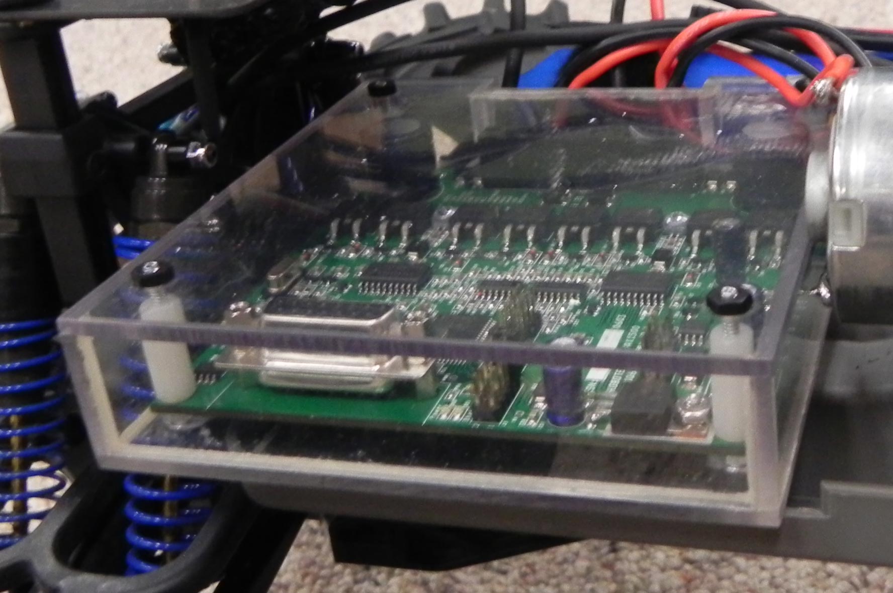
Speed Control
The Traxxas EVX-2 electronic speed control was initially used. There were two major problems with this control. First, going from forward to reverse was not reliable. Sometimes reverse would run and sometimes brakes were applied. Second, when reducing speed, the robot coasted down to the new speed. Much more reliable control was definitely required.

Based on excellent experience with AX2500 and AX2550, a RoboteQ AX500 was tried. Unfortunately, the AX500 also allowed coasting during speed changes. Apparently, it is the only RoboteQ product that does.

Polycarbonate housing for the AX1500 motor controlFinally, a RoboteQ AX1500 was installed. That provided specs well in excess of anything that this robot would experience. Pulse width was used to control the AX1500 because it required the least amount of microcontroller resources.

Satisfied with the AX1500, a polycarbonate housing was built to provide a little protection from moisture.

Compass
The first compass was a tilt compensated three axis digital unit from OceanServer. The PC software that came with the compass was very impressive. The serial output could easily be adjusted for rate and format. Even update rates and digital filter factors could be changed. It was all a lot of fun to play with.

Unfortunately, when transversing uneven ground, the sideways accelerations of the compass produced major heading changes. Lowering the compass in the chassis and playing with the filter parameters helped, but a straight course could not be obtained.
The PNI V2Xe was tried next. The major difference was that the V2Xe used a form of SPI communications. There were problems with the update rates and responses, as well as the same variable headings over uneven ground.

Finally, a Honeywell HMC6352 was used. At last there was reasonable directional control. This is not a tilt compensated compass. One big advantage is that there is an operating mode called the “Query Mode” that is very fast and allows compass updates every 20 msec.

It should be noted that there are many magnetic hazards at the Chibots RoboMagellan site. The present mast height of 22 inches is not sufficient to avoid the hazard. Every run shows some unusual behavior caused by compass errors.

Servos
Originally the servos were connected to the Propeller with Optical Isolators. Experiments indicated that the optical isolators were not needed. Now, just a 4.7 K ohm resistor is used between the Propeller pin and the servo signal line. No problems have been encountered with this arrangement.

The original Traxxas 2056 servos were replaced with Traxxas 2075 digital servos (Ebay) so that the pulse rate could be varied between 20 msec and 40 msec without impacting servo performance.

For the rear steer, a Futaba S9351 digital servo was chosen for its high torque and compatibility with the Traxxas servo horns. All of the servos are run off of the 6 volt regulator without any problems.
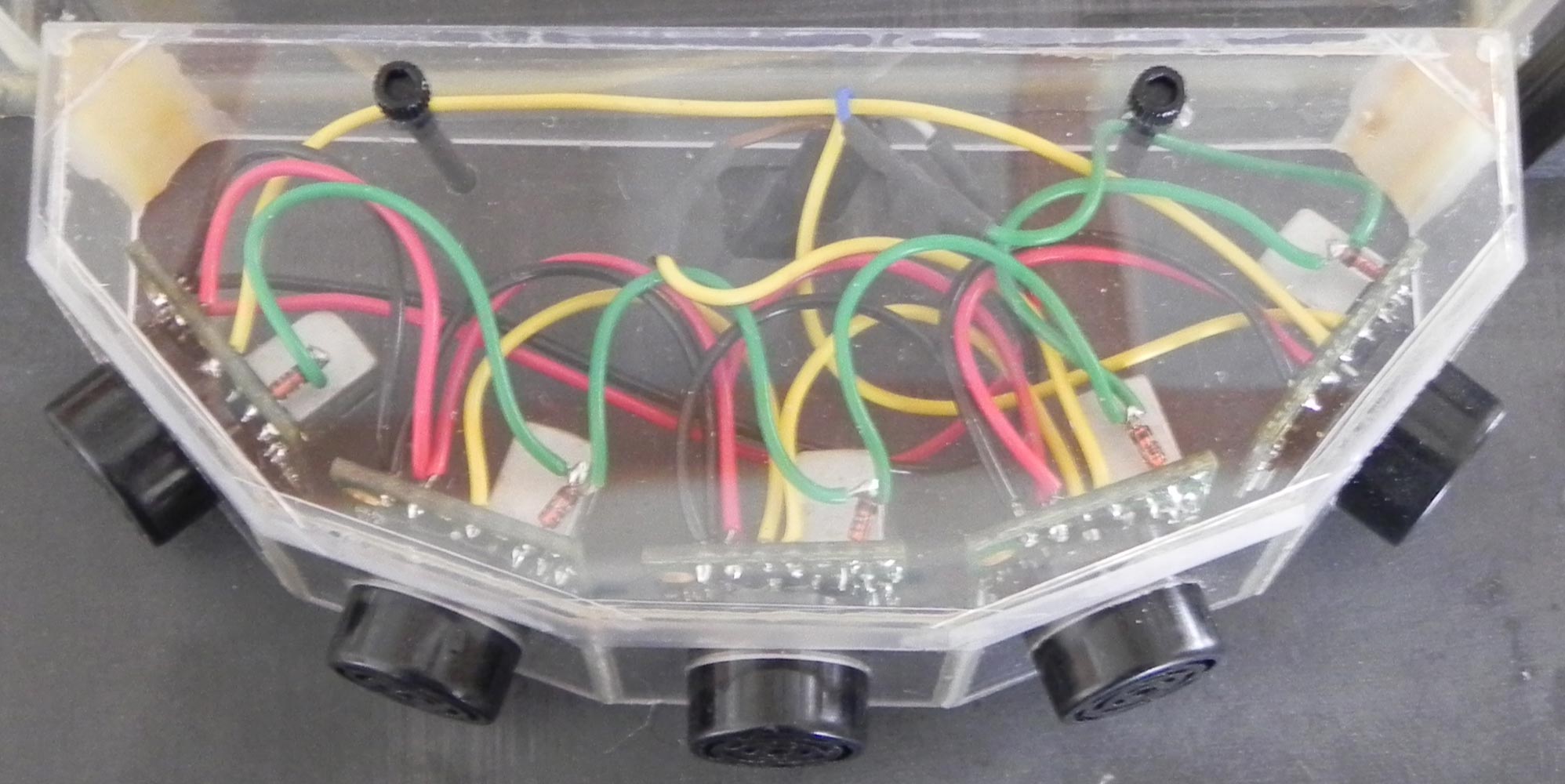
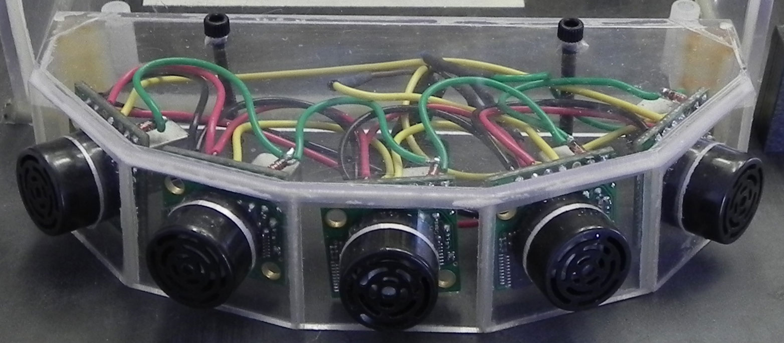
Sonar
Three MaxBotix LV-EZ1 ultrasonic proximity sensors installed for object detection and pylon location. A single pulse triggers the first LV-EZ1 and that LV-EZ1 triggers the second, and so on. All of the LV-EZ1 outputs are combined and only one pin is needed to read all of the inputs.

The Propeller counts the pulse width using a factor that results in the final count being the distance to the detected object in decimeters. If the pulse width is longer than 80 decimeters distance, the counting is terminated and the sequence is reinitiated. This is done to prevent locking the cog.

The results of the sensors do not directly control the steering or speed of the robot. The results limit the maximum right or left turn and the maximum allowable speed. Using this technique, there is little interaction between the navigation functions and the obstacle avoidance functions.

If the sonar detect an object less than three decimeters away, an escape sequence is initiated. The only control with a higher priority than the escape sequence is the kill switch. When in the escape sequence the robot performs a three point turn. Remember the three point turn from the Radio Control section above? The robot continues the three point turn until the sonar detects a clear path to continue other movements. Of course, the three point turn starts in the direction closest to the desired path.

Five sonar unit arrayThe three sonar unit was replaced with a five sonar unit using MaxBotix XL-EZ1 units to increase the detection area. The three front sensors are used for object avoidance and all five sensors are used to detect the pylons. It should be noted that the XL-EZ1 units to take about twice as long to make a reading, but do give a little better distance reception than the LV-EZ1.

Five sonar array front viewThe sonar has always been placed in a machined polycarbonate housing to maintain alignment and provide weather protection. They are angled up about 10 to 15 degrees. The top plate effectively cuts off the lower part of the sonar response cone to eliminate ground and grass detection. Even with the XL-EZ1 units, the pylons can not be detected more than 1.2 to 1.3 meters away.

Poor detection distance at speed is the major limiting factor in the robots performance. Work is continuing in this area.

GPS
Originally, the EB-85A (now the MV-M8) was the popular choice. Particularly useful was the 115,200 bps serial transfer rate and the feature that allowed settings to be saved to flash. The EB-85A did not prove to be an effective GPS unit for robot navigation.

The EB-85A was replaced with an EM-406A that seemed to work better. With either GPS it appears that performance is increased if the GPS unit is mounted on the carbon fiber chassis plate instead of the perforated circuit board. There is a forum post that indicates that the Propeller may adversely affect near GPS performance.

For 2010, the EM-406A was replaced with the u-Blox 5 based GS407. The performance is slightly better than the the EM-406A, and it updates four times a second. The faster update rate helps when approaching way points and changing way points. Another advantage of the u-Blox 5 is it's support software. The casual user has much more control of the characteristics of the GPS output.

I am currently looking at the Media Tek MT3329 which may prove to be better than the u-Blox.
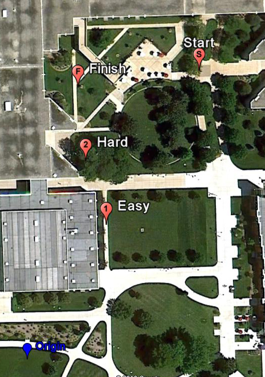
Latitude and Longitude
Latitude and longitude numbers produced by the GPS unit are very intimidating. In order to ease the calculations and produce numbers more readable, an “artificial origin” is chosen just southwest of the RoboMagellan course. The Latitude and Longitude of the artificial origin as well as the degrees per decimeter for Latitude and degrees per decimeter Longitude are entered into the program as constants.

For each new location, Google Earth is used to locate the artificial origin and an online program is used to calculate degrees per meter for Latitude and Longitude. During ASCII to integer conversion of the NEMA sentences, only the difference between the actual readings and the artificial origin are calculated and converted to decimeters. Decimeter GPS distances are unrealistic, but sonar and encoder decimeter readings are reasonable and having two different standards of measurement in the same program would be very confusing.

Chicago RoboMagellan 2009 Pylon locations along with the artifical originFor example, the artificial origin for the Chibots 2009 competition was 85°16.32', 41°4.59'. So the start location was (927,1551). That means that the start was 927 decimeters East of the artificial origin and 1551 decimeters North of the artificial origin. Continuing, the easy pylon was (425,724), the hard pylon was (314,1065) and the finish pylon was (272,1459).

Calculations from GPS data was more difficult that originally anticipated. The distance from the present location to the way point is fairly straightforward since good square root functions exist. On the other hand, arc Tan function was much more difficult. Someone posted the original code which was very time consuming and not very accurate. My arc Tan function is now on it's fourth version of code developed by someone else and posted on the Propeller forum. Remember that I am not a programmer. Without others posting code, this project would have been abandoned a long time ago. Also note that there are four quadrants to worry about. The robot must be tested in each quadrant after any code changes are made. It is not unusual to have two quadrants correct and two quadrants 180° off. The last time I change much code, there were three quadrants correct and one quadrant was 180° off. Just test, test, test.
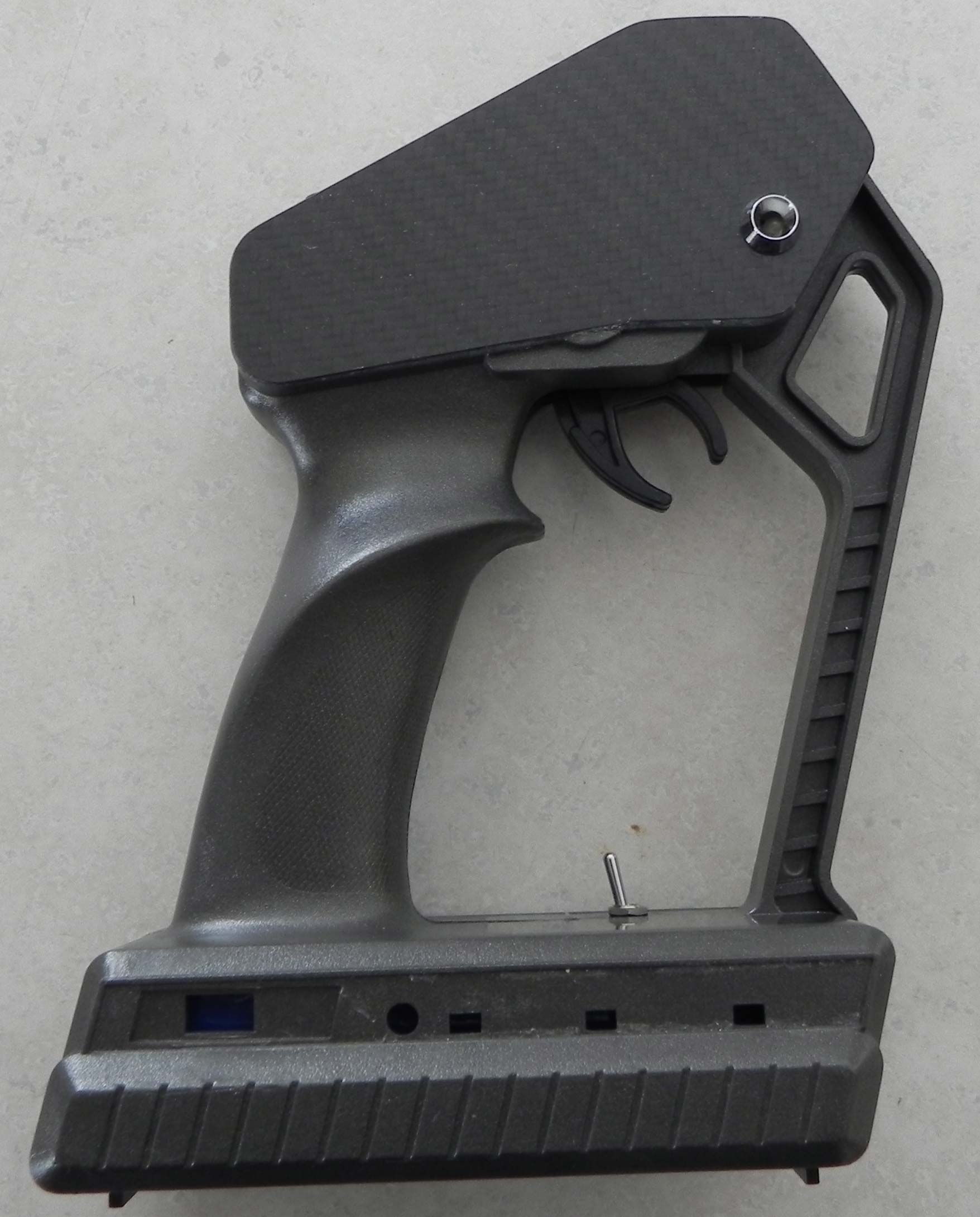
Kill Switch
The rolling code remote that has been used in many of my sumo robots was used. Because the distances are greater in RoboMagellan that sumo, a vertical antenna on the receiver is required. The distance of the remote is limited to about 100 feet, so the operator must stay reasonably close to be effective. Please note that the kill switch has a much greater useable distance than the original R/C transmitter.

"Dead Man" kill switch from a Traxxas transmitterIf any button on the remote is pushed, the motor is immediately stopped, but the rest of the programs continue normally. A second button push releases the motor to run normally. That way, the robot can be paused for any reason and restarted exactly where it left off.

A stock Traxxas transmitter was gutted and the rolling code remote installed. The original throttle control was used as the "Dead Man" kill switch. Logic for the throttle control and transmitter is provided by a simple BS2 program.

Resources
All of the cogs are being used. A spare cog would be available if the R/C receiver was not used. A second cog could be freed by using a slower uSD read/write function.
The RCOut Cog uses about 10 msec of the 20 msec between servo pulses. If the servo pulses are stretched to 40 msec, then a substantial amount of time is available to perform more functions.

The GPS NEMA Cog uses about 50 to 75 msec every GPS update. There is time available for ten GPS updates per second and additional functions.
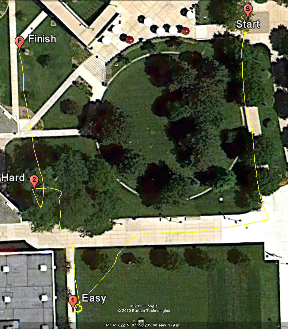
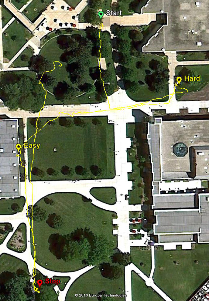
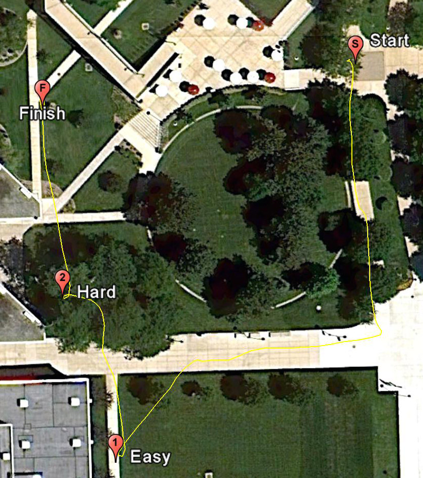
The program, written entirely in Spin, uses about 71% of the available RAM.
Although the program is fairly complex and probably rather inefficient, there is still substantial resources available on the Propeller for many more features.

Navigation Commands
Programming the Propeller at an event is very simple. There are only two commands, a Nav command for Navigate, and an NCone command to Navigate to a cone. The two commands have only three inputs each. There is an East decimeter input, a North decimeter input, and a speed input. So Nav(927, 1551, 40) command to robot to go to a location 927 decimeters East of the artificial origin, 1551 decimeters North of the artificial origin, at a speed of 40%. Below is the programming for the fast run at ChiBots RM 2009 competition:

Nav(927, 1551, 40) ' Start
Nav(934, 1260, 40)' Mid Sidewalk
Nav(978, 1004, 40)' Corner
Nav(604, 940, 40)' Turn in
NCone(425, 724, 40)' Easy Pylon
Nav(386, 1047, 40)' Center of trees
NCone(314, 1065, 40)' Hard Pylon
NCone(272, 1459, 40)' End Pylon

That is the total programming done at an event!

Results
ChiBots first RoboMagellan contest was held on June 7, 2008. Since my robot was not capable of autonomous operation, we just sat around, talked and posed for photos.

ChiBots second RoboMagellan contest was held on November 8, 2008. Apparently, I had miscalculated the GPS offset location, so the robot was looking for way points in Cicero. The GPS guidance was disabled and the course was attempted using just the compass and encoder. In practice, performance was little better than horrible. For the scoring runs, the encoder stopped working and the robot drove South until it encountered the nearest construction fencing.

Google Earth display of the first run at the ChiBots 2009 RoboMagellan contestChibots third RoboMagellan contest was held on August 15, 2009. Now the robot is capable of autonomous navigation. The runs are documented on video. Please watch Youtube video for Run 1 and Youtube video for Run 2. Also, Google Earth plots can be viewed for Run 1 and Run2. The first run was done at slow speed and the first pylon was missed. That way point was moved West 2 meters and North 1 meter and the speed was doubled for the second run. The raw time for the second run was 1:45 and two 0.5 multipliers gave an adjusted final time of 26 seconds.

ChiBots 2010 RoboMagellan Run 2ChiBots fourth RoboMagellan contest was held on July 24, 2010. When measuring the GPS locations of the pylons, it was discovered that the finish pylon was actually South of the artificial origin. I figured that a simple calculation could make up for the difference. The results of that calculation is shown in Run 1. So all of the way points were re measured and Run 2 came out better. Note the line in the Google Earth plot from the finish pylon to the center of the round mound. Being lazy, I programmed the robot to pause for a minute at the finish pylon, then return to to the location where the Peoria group had set up their tent. Not settling for a slow run, the speed was increased for the third run and the result was the robot had to be stopped when it entered the flower garden. Hopefully, no videos or photos exist. Oh, well, there is always next year.