Executioner
| Late in 2004 work began on a suitable replacement for Excuse. Since Excuse was originally designed for the 3 pounds sumo class, a purpose built 3 Kg sumo would be far more competitive. The primary design goal would be substantially higher speeds and more weight built in to the structure. |
| There are many, very powerful, small electric motors available for R/C cars and airplanes. The major problem with these motors is that there were designed to turn most efficiently in only one direction, counter clockwise. That is, they have advanced timing built into the motor brushes. The motors in my robots will need to run in both directions, counter-clockwise on the left side of the robot and clockwise on the right side of the robot. So neutral timing or, preferably, advanced counter clockwise on the left side and advanced clockwise on the right side of the robot. |
 The first chassis was powered by four Speed 380 motors from The Robot Marketplace and four PGHM-09 gearboxes (no longer available) from Lynxmotion. Also, a gear puller and a timing adjustment tool were acquired. The major problem with this arrangement was that the axles had too much play. High precision bearings reduced the play, but the axles could not hold the tires square to the ground for maximum traction. The first chassis was powered by four Speed 380 motors from The Robot Marketplace and four PGHM-09 gearboxes (no longer available) from Lynxmotion. Also, a gear puller and a timing adjustment tool were acquired. The major problem with this arrangement was that the axles had too much play. High precision bearings reduced the play, but the axles could not hold the tires square to the ground for maximum traction. |
| In March, 2005, a major change in robot construction techniques arrived in the form of a Smithy Midas 1220 Ltd with a three axis digital readout. Now, much more advanced work is possible. The chassis with the Speed 380 motors was boxed up and forgotten. |
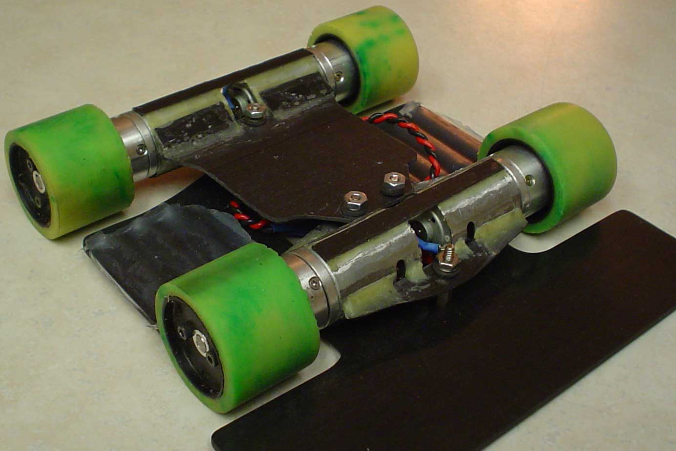
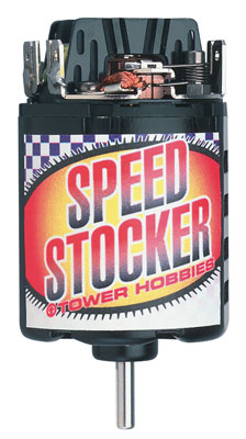 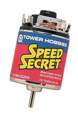 R/C car motors and Lynxmotion 27:1 gearboxes (PGHM-14) were the next step. Stock wind (27 turn) R/C car motors do not come with adjustable timing and adjustable timing motor cans only come with much higher current armatures, requiring much more powerful motor controls. The logical solution is a stock armature in a modified motor can. Tower Hobbies Speed Stocker 27 Turn Racing Motors provided the armatures and Tower Hobbies Speed Secret 14T Quad Modified Motors provided the cases. The two fit together like there were made for each other. The speed control that I have been using was capable of 18 amps continuous per side. With double the MOSFETs, 18 amps per motor should be ample. R/C car motors and Lynxmotion 27:1 gearboxes (PGHM-14) were the next step. Stock wind (27 turn) R/C car motors do not come with adjustable timing and adjustable timing motor cans only come with much higher current armatures, requiring much more powerful motor controls. The logical solution is a stock armature in a modified motor can. Tower Hobbies Speed Stocker 27 Turn Racing Motors provided the armatures and Tower Hobbies Speed Secret 14T Quad Modified Motors provided the cases. The two fit together like there were made for each other. The speed control that I have been using was capable of 18 amps continuous per side. With double the MOSFETs, 18 amps per motor should be ample. |
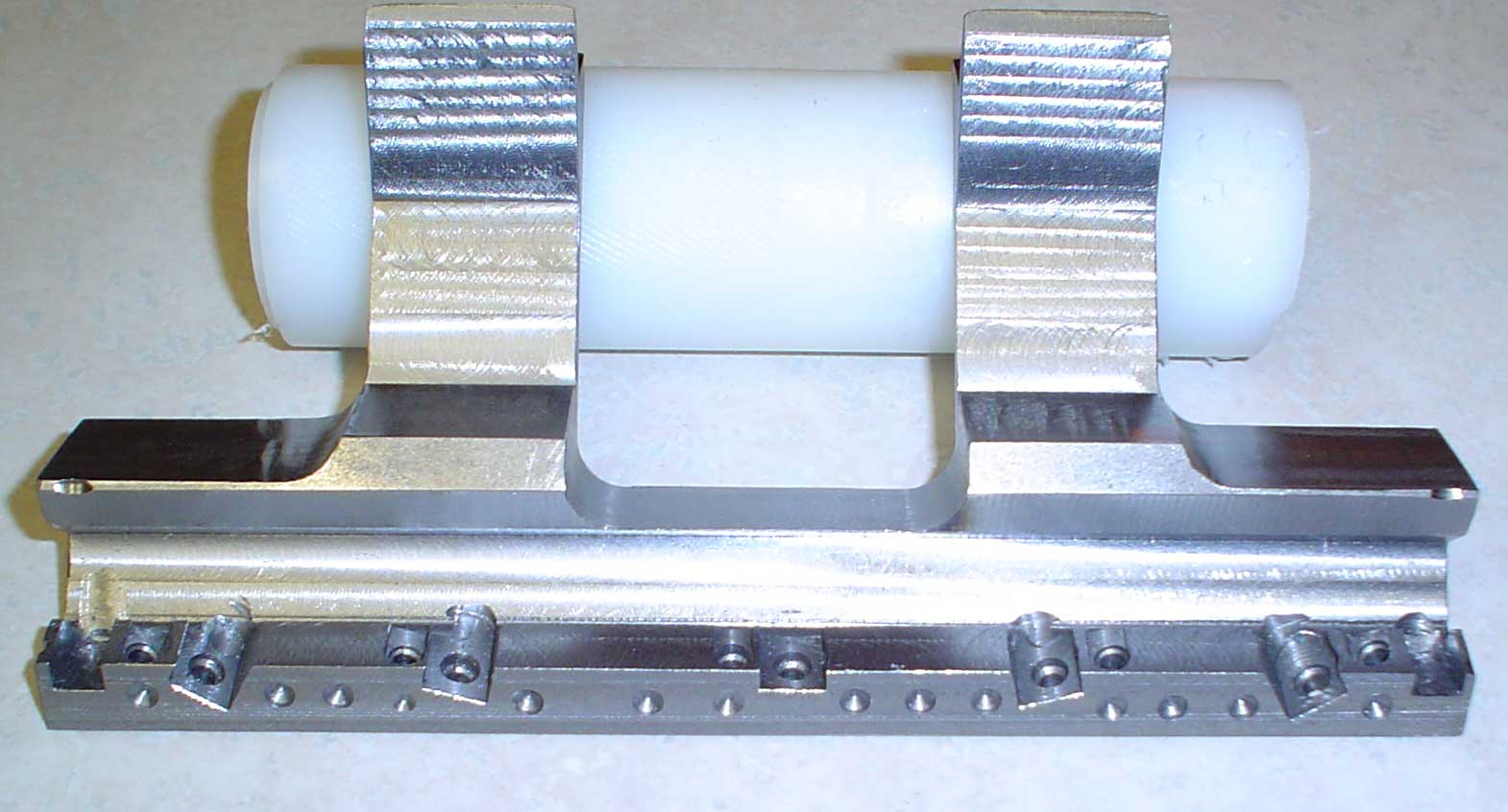
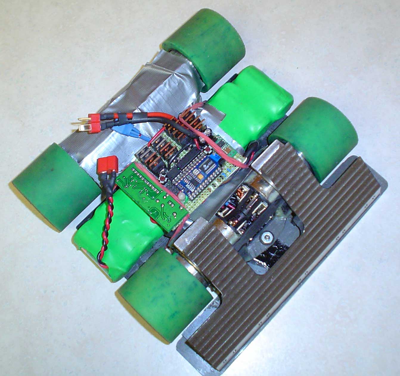
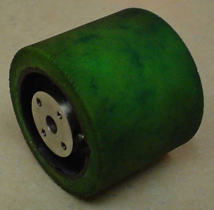 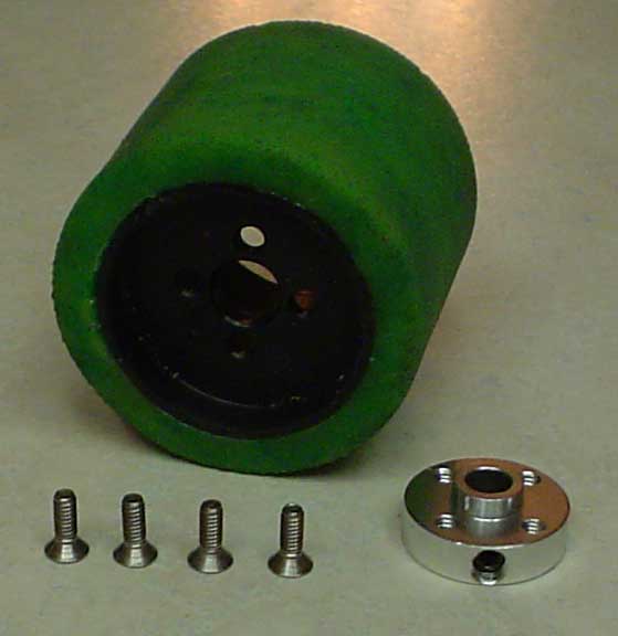 New wheels were machined out of Delrin. The wheels were about 1.5” diameter and 1.65” long. They extended 1.25” over the gearboxes. Aluminum hubs were placed outside the wheels for easy access to the axle set screws. New wheels were machined out of Delrin. The wheels were about 1.5” diameter and 1.65” long. They extended 1.25” over the gearboxes. Aluminum hubs were placed outside the wheels for easy access to the axle set screws.
A chassis was built similar to Excuse II and ten GP3700 NIMH batteries were installed. Initial runs were awesome! 130 inches per second speed with almost instantaneous acceleration and deceleration must be seen to be appreciated. Accidentally, I programmed in a two second run. The robot careened off of two dining room chairs, the dining room table, and two walls. Once it stopped, the gearboxes did not sound very good. A disassembly of the boxes revealed many stripped nylon planet gears. |
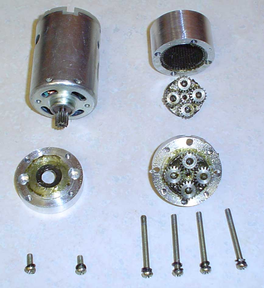 It was obvious in the photos on the web site that the current Lynxmotion PGHM-14 gearboxes were different from the ones that I just stripped. A few days later, four new gearboxes arrived. Upon disassembly, it was discovered that they had four planet gears per stage and the planet gears were metal. That is how they achieved the 5.9 foot/pound instantaneous torque rating. It was obvious in the photos on the web site that the current Lynxmotion PGHM-14 gearboxes were different from the ones that I just stripped. A few days later, four new gearboxes arrived. Upon disassembly, it was discovered that they had four planet gears per stage and the planet gears were metal. That is how they achieved the 5.9 foot/pound instantaneous torque rating.
To achieve 20 cm width, the snap ring and washer were removed from the axles, .100” was removed from the back plate, and .050” was removed from the front plate. Also, the OD of the gearbox was reduced from 1.42” to 1.34” to better fit the wheels. The modified gearboxes were assembled onto the motor using new M3.0 bolts and lock washers with Loctite 290 between the pinion and motor shaft, and between the back plate and the motor case. The robot was now 19.8 cm wide. |
| Four of the batteries were removed to slow the thing down to a manageable speed. The remaining six GP3700 MINH cells should be more than enough. The new gearboxes were briefly broken in and a new speed test produced 85 inches per second. The chassis, motors, gearboxes, and batteries weighed 4 pounds 8.8 ounces. A push test resulted in over 13 pounds of force. This is more in line with my original design goals. |
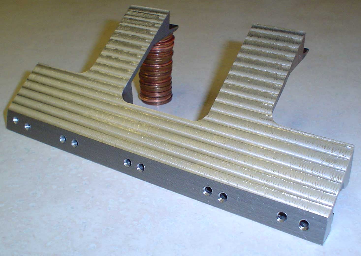 The front bumper is machined out of a hunk of ½” x 6” 1018 steel. Since this was my first serious milling project, a partial bumper was machined out of aluminum to get practice in the order of cuts and hold down techniques. Once work on the steel bumper began, it was surprising how much longer it took to mill steel than aluminum. Also, the original High Speed Steel end mills soon gave way to carbide end mills. It took several broken end wills to work out the proper techniques. The front bumper is machined out of a hunk of ½” x 6” 1018 steel. Since this was my first serious milling project, a partial bumper was machined out of aluminum to get practice in the order of cuts and hold down techniques. Once work on the steel bumper began, it was surprising how much longer it took to mill steel than aluminum. Also, the original High Speed Steel end mills soon gave way to carbide end mills. It took several broken end wills to work out the proper techniques. |
 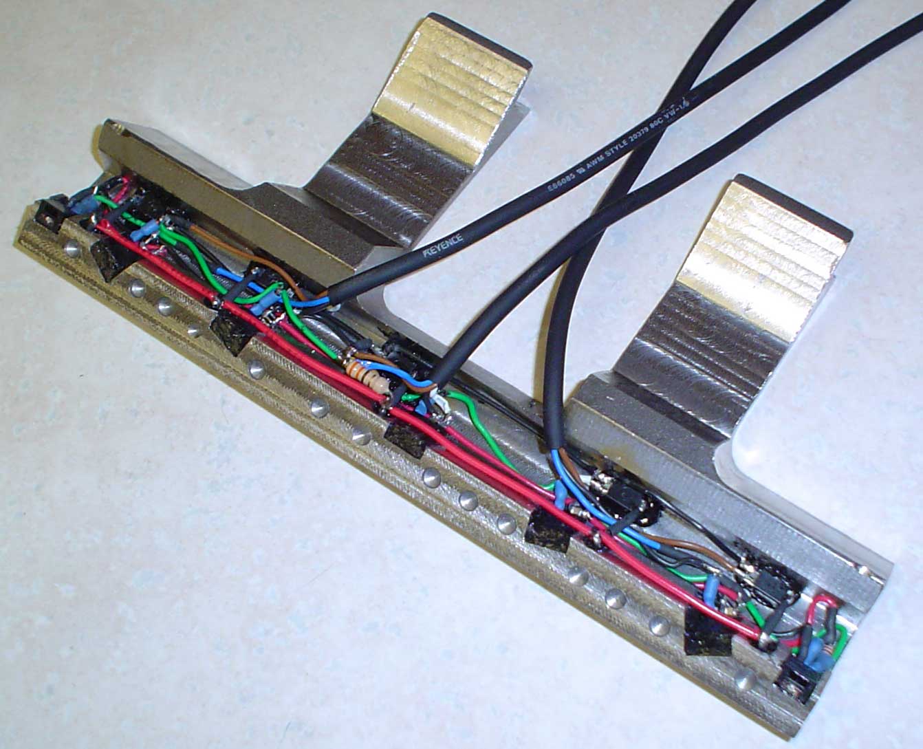 As in Extrasensory, precise locations for the IR LEDs and IR receivers were machined into the bumper. For the first time in any of my sumo robots, line sensors were included in the bumper. The line sensors work very well, but, so far, they are not included in the software. I still haven’t figured out how to use them to benefit the robot. As in Extrasensory, precise locations for the IR LEDs and IR receivers were machined into the bumper. For the first time in any of my sumo robots, line sensors were included in the bumper. The line sensors work very well, but, so far, they are not included in the software. I still haven’t figured out how to use them to benefit the robot. |
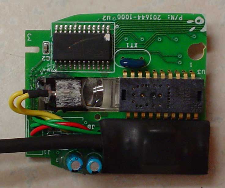 An MX310 optical mouse was included. This time an ezMOUSE from Multilabs was used to convert the PS/2 from the mouse to serial for the Stamp. The connectors were removed from the ezMOUSE and the printed circuit board was cut down. Four wires from the MX310 to the ezMOUSE and four more from the ezMOUSE to the Stamp board completed the mouse wiring. A little heat shrink around the ezMOUSE provided electrical insulation, and a little silicone glue attached the ezMOUSE directly to the MX310 board. An MX310 optical mouse was included. This time an ezMOUSE from Multilabs was used to convert the PS/2 from the mouse to serial for the Stamp. The connectors were removed from the ezMOUSE and the printed circuit board was cut down. Four wires from the MX310 to the ezMOUSE and four more from the ezMOUSE to the Stamp board completed the mouse wiring. A little heat shrink around the ezMOUSE provided electrical insulation, and a little silicone glue attached the ezMOUSE directly to the MX310 board. |
 By the end of January, 2006, all electrical and mechanical assembly was completed. Testing and software setup revealed that the robot had 85 inches per second speed along with awesome acceleration, braking, and turning potential. At this stage, the name “Executioner” seemed to fit much better than any others that had been suggested. By the end of January, 2006, all electrical and mechanical assembly was completed. Testing and software setup revealed that the robot had 85 inches per second speed along with awesome acceleration, braking, and turning potential. At this stage, the name “Executioner” seemed to fit much better than any others that had been suggested. |
 Software testing under search conditions indicated that the main control loop runs 10,000 times in 180 seconds. That is 18 milliseconds per loop. Actually, about a third of that time is used up in mouse communications. Software testing under search conditions indicated that the main control loop runs 10,000 times in 180 seconds. That is 18 milliseconds per loop. Actually, about a third of that time is used up in mouse communications.
One changes were made as the result of the initial tests. The MX310 mouse was not as reliable as previous robots, so a 50 ohm resistor was added to increase current to the LED. The resistor approximately doubles the current in the MX310 IR LED. A test MX310 ran for 24 hours continuously at the doubled current without failure. |
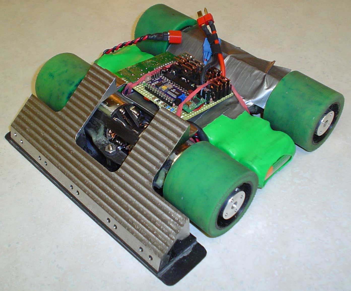
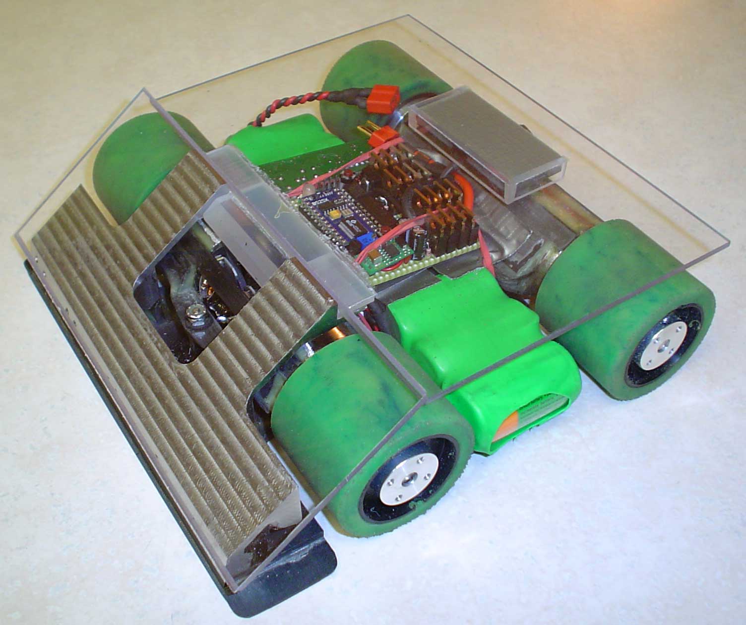
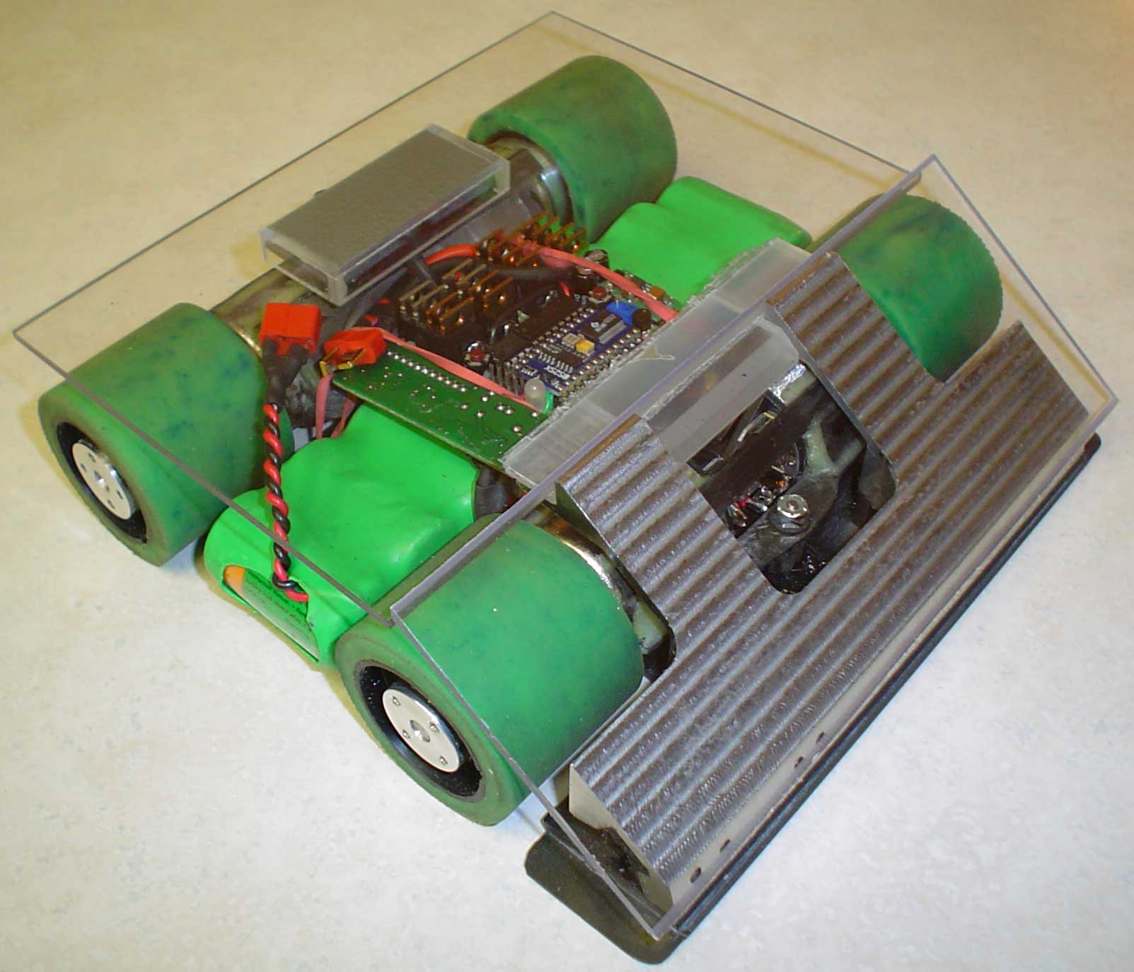 Executioner was covered with 1/8” clear polycarbonate. Polycarbonate was used because it is heavier than the carbon fiber, it absorbs IR and sonar better than carbon fiber, and it looks good. Final weight was 6 pounds 1 ounce, or 2.750 Kg. Executioner was covered with 1/8” clear polycarbonate. Polycarbonate was used because it is heavier than the carbon fiber, it absorbs IR and sonar better than carbon fiber, and it looks good. Final weight was 6 pounds 1 ounce, or 2.750 Kg. |
 Pushing the two buttons and counting red or green LED flashes was getting very tiresome, particularly when there are eight or nine different start routines. The first attempt to simplify this process was a Comfile CLCD-216 display. The advantage of this particular LCD was the 115.2 Kbps serial communications to the Stamp. Pushing the two buttons and counting red or green LED flashes was getting very tiresome, particularly when there are eight or nine different start routines. The first attempt to simplify this process was a Comfile CLCD-216 display. The advantage of this particular LCD was the 115.2 Kbps serial communications to the Stamp. |
| For initial testing, the LCD was placed in a box and a 4 wire USB male/female plug was used to connect the box to Executioner. The LCD displayed the sensor outputs, mouse outputs, and the present start routine. Two buttons on the box controlled the start routine selection and the actual start.
Executioner’s first outing was the May 6, 2006 event in Peoria. During the competition, the mouse lost contact with the surface too many times and ordered Executioner to spin to avoid a perceived threat. All of that spinning resulted in the rear tires coming off of the wheels. In order to cure the tire problem, four new wheels were made. New polyurethane tires were molded with a hardness of 20 Shore A (the originals were 10 Shore A). After removing the tires from the mold, the tires were superglued to the wheels. The original tires were superglued, also. All future testing was done with the new tires and no more problems were encountered. Further investigation revealed two major software problems with the optical mouse. One of the errors goes back to the original software that was used two years ago. Once those errors were corrected, the mouse response resulted in repeatable results. Presently, the thresholds for evasive action are being evaluated and updated. |
  The external box for the LCD was too much of a hassle, so an attempt was made to reduce the thickness of the LCD and mount it on Executioner’s top polycarbonate plate. Two recessed push buttons were also installed. Before that modification was completed, I received a new Graphic Touch Screen Display from PDA, Inc. Their web site is simmetry.com and their display is available through eBay from "dgodrik". The processor on the Graphic Touch Screen Display can store up to 26 screens. The screens are created on provided PC software and downloaded directly to the display for saving. There are also several templates in the Graphic Touch Screen Display for interpreting and reporting the touch screen inputs. It takes only four ASCII characters (plus Carriage Return) to load a saved screen and a template. Touch Screen inputs are saved until the Stamp requests they be returned. It is very nice and easy to use! The external box for the LCD was too much of a hassle, so an attempt was made to reduce the thickness of the LCD and mount it on Executioner’s top polycarbonate plate. Two recessed push buttons were also installed. Before that modification was completed, I received a new Graphic Touch Screen Display from PDA, Inc. Their web site is simmetry.com and their display is available through eBay from "dgodrik". The processor on the Graphic Touch Screen Display can store up to 26 screens. The screens are created on provided PC software and downloaded directly to the display for saving. There are also several templates in the Graphic Touch Screen Display for interpreting and reporting the touch screen inputs. It takes only four ASCII characters (plus Carriage Return) to load a saved screen and a template. Touch Screen inputs are saved until the Stamp requests they be returned. It is very nice and easy to use! |
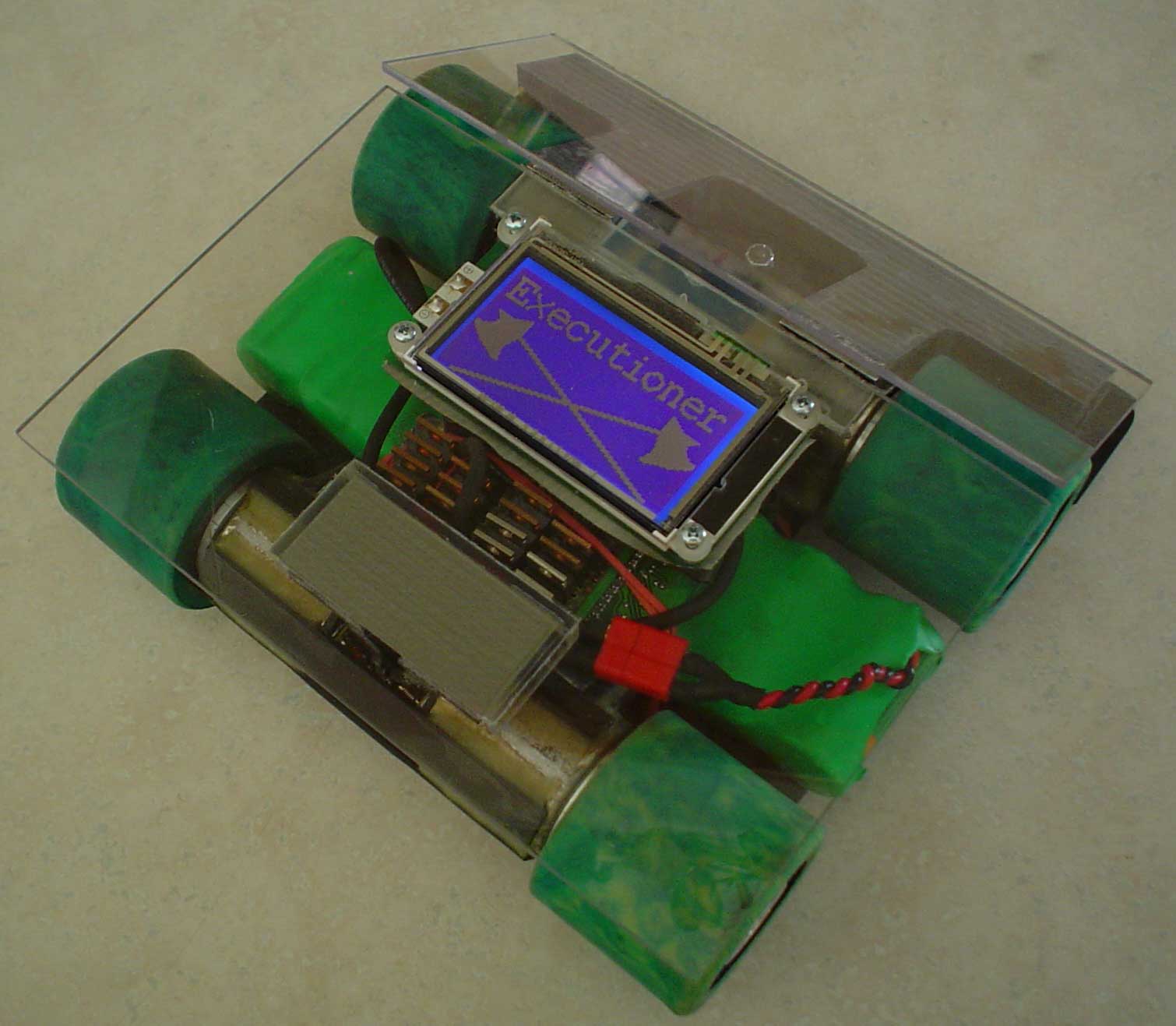
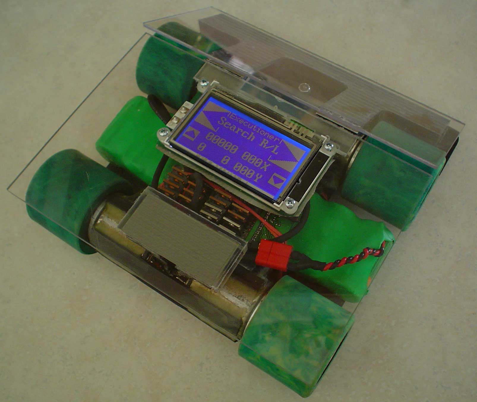
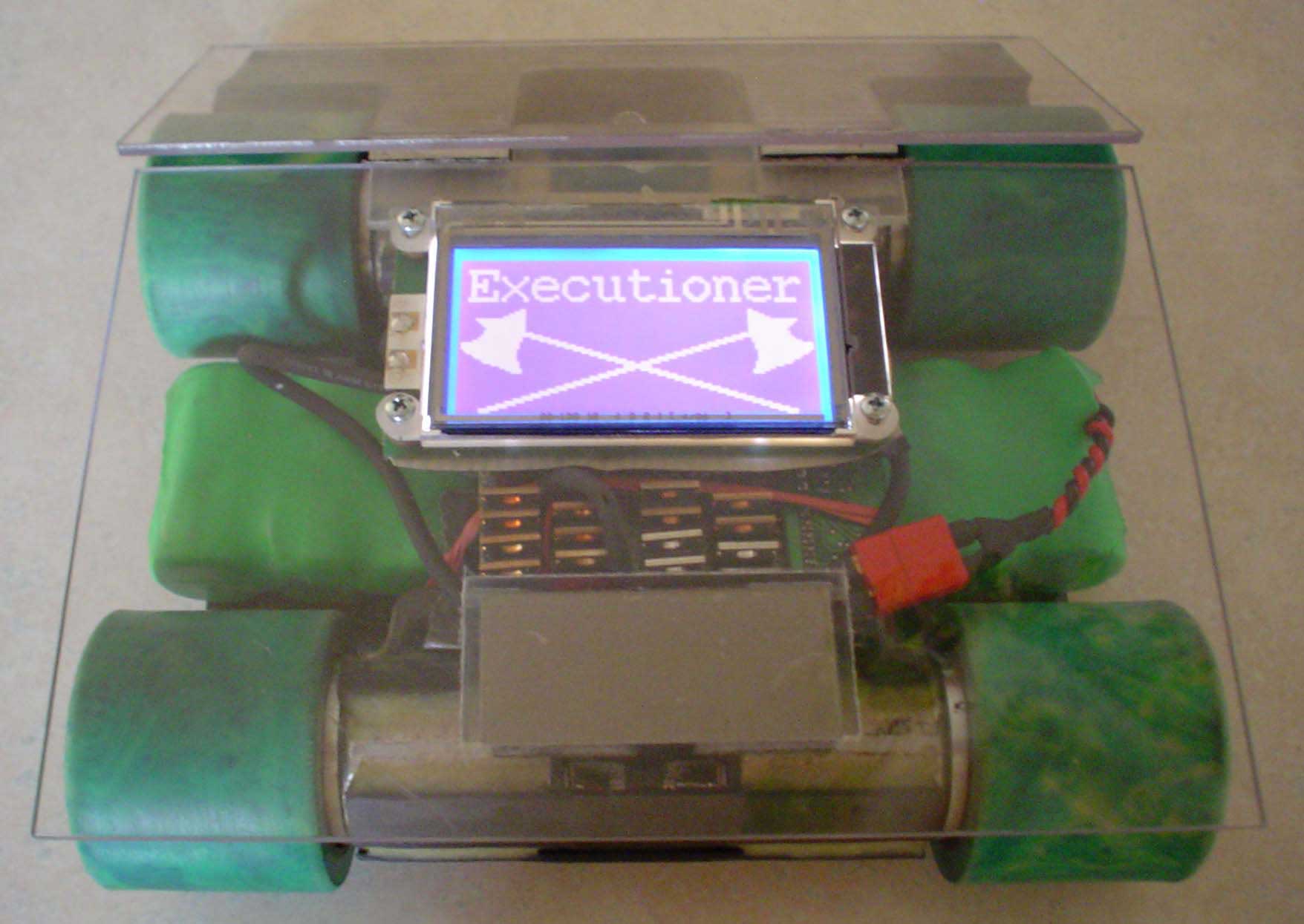 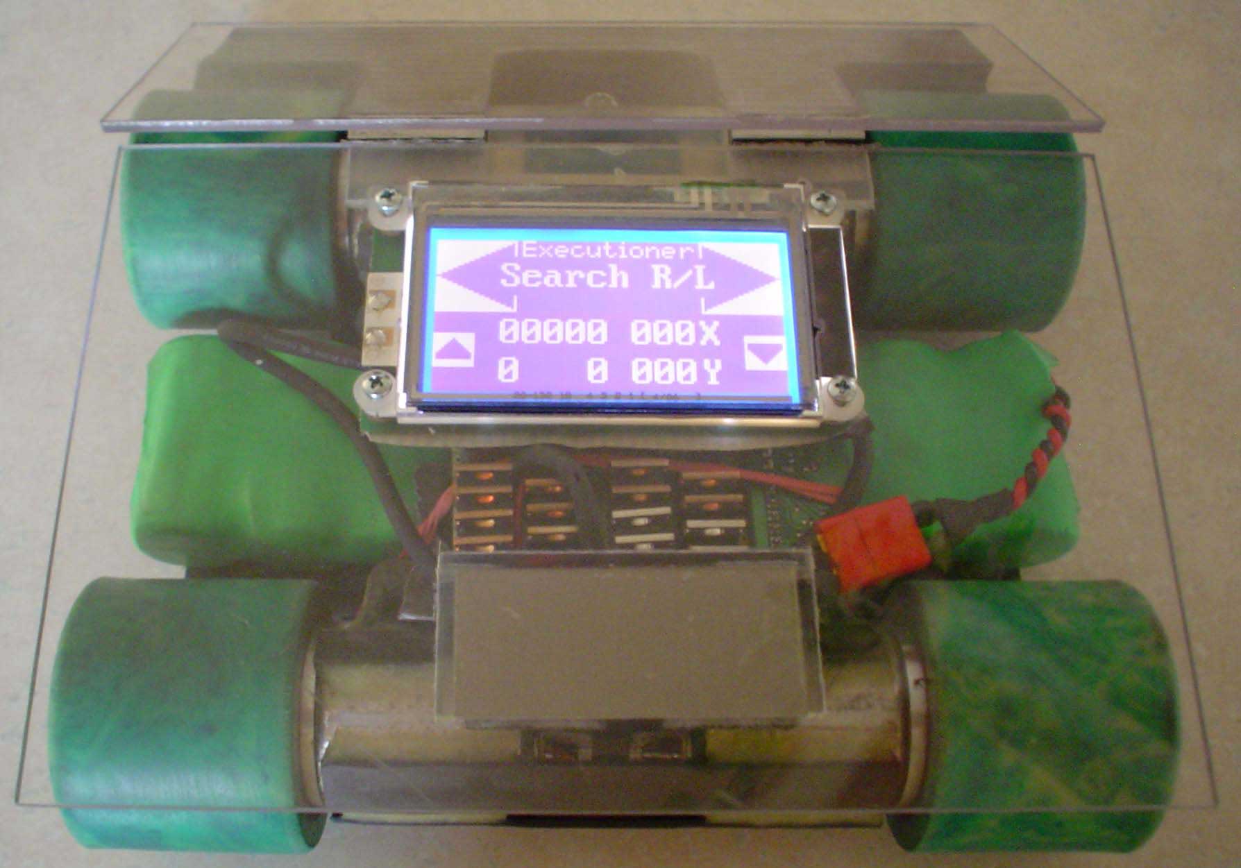 Of course the first screen has to be the name “Executioner” with the crossed axes. The start screen displays “Executioner” at the top center. Immediately below “Executioner” is the presently chosen start routine. In this case the routine is “Search R/L”. Pushing the big arrow to the right of the start routine initiates the five second countdown and the runs “Search R/L” to the right. The left arrow runs “Search R/L” to the left. The “00000” are the front sensors. In this case, they do not see anything. Immediately below is “0 0” which is the two front line sensors. Next to that are “000X” and “000Y” which display the mouse outputs. The up and down arrows increment the start routines. Of course the first screen has to be the name “Executioner” with the crossed axes. The start screen displays “Executioner” at the top center. Immediately below “Executioner” is the presently chosen start routine. In this case the routine is “Search R/L”. Pushing the big arrow to the right of the start routine initiates the five second countdown and the runs “Search R/L” to the right. The left arrow runs “Search R/L” to the left. The “00000” are the front sensors. In this case, they do not see anything. Immediately below is “0 0” which is the two front line sensors. Next to that are “000X” and “000Y” which display the mouse outputs. The up and down arrows increment the start routines. |
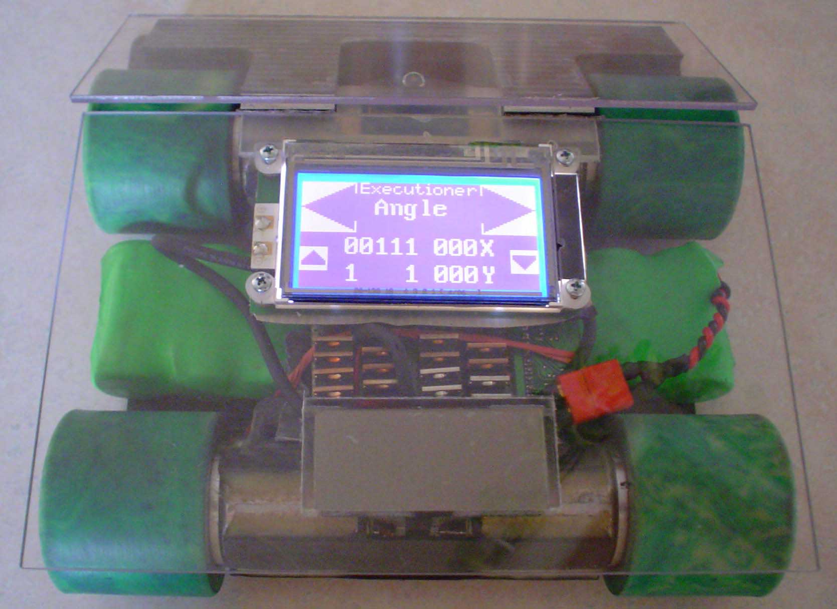 This photo shows the Graphic Touch Screen Display for the “Angle” start routine. The center, right center, and right sensors see an object, and both line sensors see the surface. Once one of the start buttons is pushed, the screen displays a countdown 5, 4, 3, 2, 1. If the screen is touched during the countdown, then the program and display return to the previous start screen. This photo shows the Graphic Touch Screen Display for the “Angle” start routine. The center, right center, and right sensors see an object, and both line sensors see the surface. Once one of the start buttons is pushed, the screen displays a countdown 5, 4, 3, 2, 1. If the screen is touched during the countdown, then the program and display return to the previous start screen. |